Power Transmission Mechanism for Walk Behind Lawnmower

Inactive Publication Date: 2010-08-12
IHI SHIBAURA MACHINERY CORP
View PDF6 Cites 11 Cited by
  • Summary
  • Abstract
  • Description
  • Claims
  • Application Information

AI Technical Summary

Benefits of technology

[0019]According to claim 1, in a walk behind lawnmower for mowing lawns that bifurcates a power from an engine and transmits it to drum-type wheels and a reel cutter, each of the first power transmission passage for transmitting the power from the engine to the drum-type wheels and the second power transmission passage for transmitting the power from the engine to the reel cutter has a variable speed structure for changing a rotating speed of each of driving shafts. Consequently, the rotation of the drum type wheels can be assuredly changed to the low speed by a dedicated variable speed structure, and the lawnmower can be started and driven at stable low speed even if moving wheels having large diameters is used during the moving travel, as well as the sudden starting when engaging the clutch can be prevented and the stable travel is easily achieved. Especially, when loading the machine body thereof on a truck bed during moving between the agricultural fields, the loading work can be performed at low speed without stopping the engine over a long time, and the decrease in the working efficiency due to the operation mistake or the like can be avoided. Further, the rotation speeds of the drum type wheels and the reel cutter can be separately changed, and even when the work is performed at the rugged agricultural field and the work is performed by the unskilled worker, the rotation speed of the reel cutter is kept at high speed and the working travel can be performed at low speed by lowering only the traveling speed. As a result, the cut surface of the lawns is even and smooth, and the lawns are not directly dropped, thereby enhancing the finish and growth efficiency of the lawns. Especially, the mowing pitch, the hoisting of the sand or the like can be sensitively controlled, by adequately combining each of the variable speed stages of the drum type wheels and the reel cutter, and more sensitive management of the lawns can be performed by using one walk behind lawnmower, thereby being able to substantially reduce the cost for managing the lawns.
[0020]According to claim 2, the first power transmission passage has a selective mesh type speed changing gear system as the variable speed structure for traveling and has a gearbox casing for incorporating the variable speed structure, as well as the second power transmission passage is provided so that it passes through the gearbox casing. Consequently, a speed changing gear system brings smaller power transmission loss than an endless variable speed mechanism such as hydraulic or belt variable speed one can be utilized for the traveling variable speed through the first power transmission passage, thereby being able to achieve a good traveling variable speed performance. Further, the second power transmission passage can ensure a part of the passage by using the gearbox casing through which the first power transmission passage passes, so that configuration space needed for setting the second power transmission passage can be reduced and the power transmission mechanism can be compact.
[0021]According to claim 3, the gearbox casing incorporates the differential unit for differ

Problems solved by technology

However, in both technologies, the power transmission mechanism is configured mainly for travel while working at agricultural field (hereinafter, referred to as “working travel”), thereby causing the following problems.
However, it is hard to start and drive the machine body thereof at the given speed by changing the higher speed to the lower speed suitable for the moving wheels having the larger diameters, by only controlling the engine rotation speed, so that sudden starting when engaging a clutch cannot be prevented and stable travel is hard to be achieved.
In this case, since when loading work is performed at low speed over a long time by decreasing the engine rotation speed, the engine is prone to be stopped, the loading work must be performed at high speed, thereby leading to the pro

Method used


Image

  • Power Transmission Mechanism for Walk Behind Lawnmower
  • Power Transmission Mechanism for Walk Behind Lawnmower
  • Power Transmission Mechanism for Walk Behind Lawnmower

Examples


Embodiment Construction

[0057]Next, embodiments of the present invention will be described.

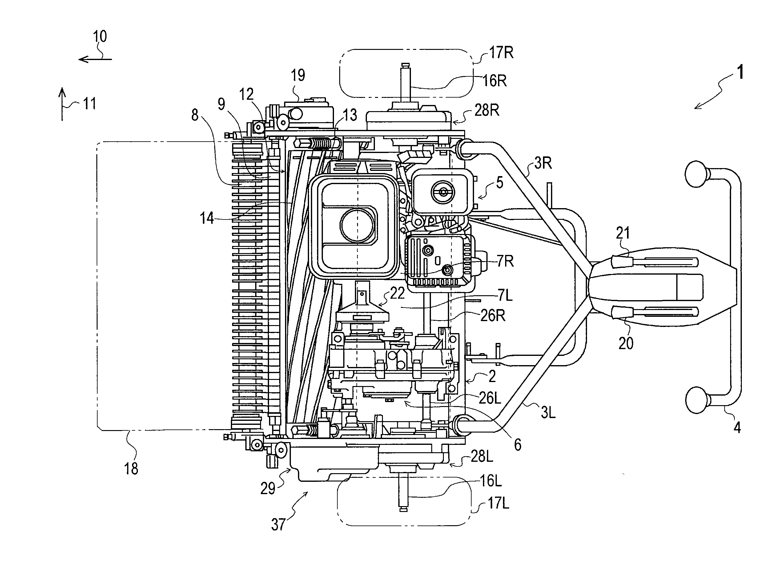
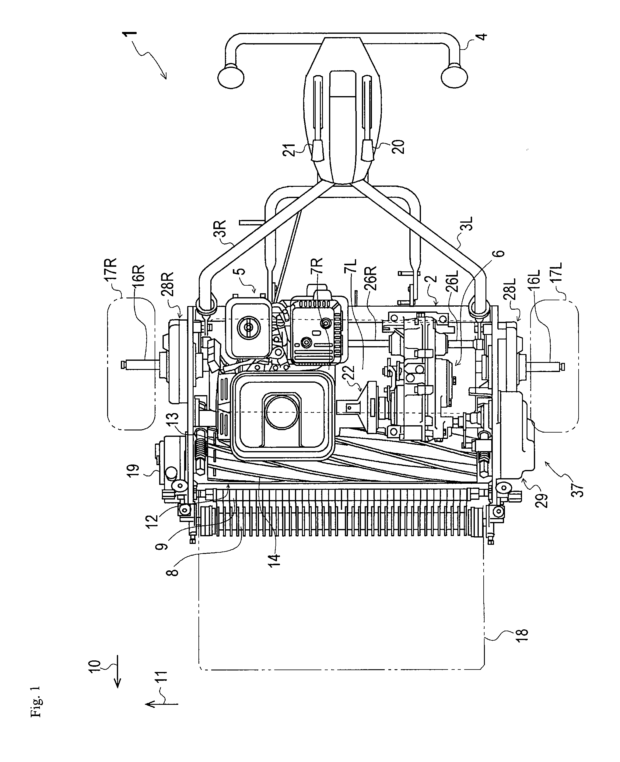
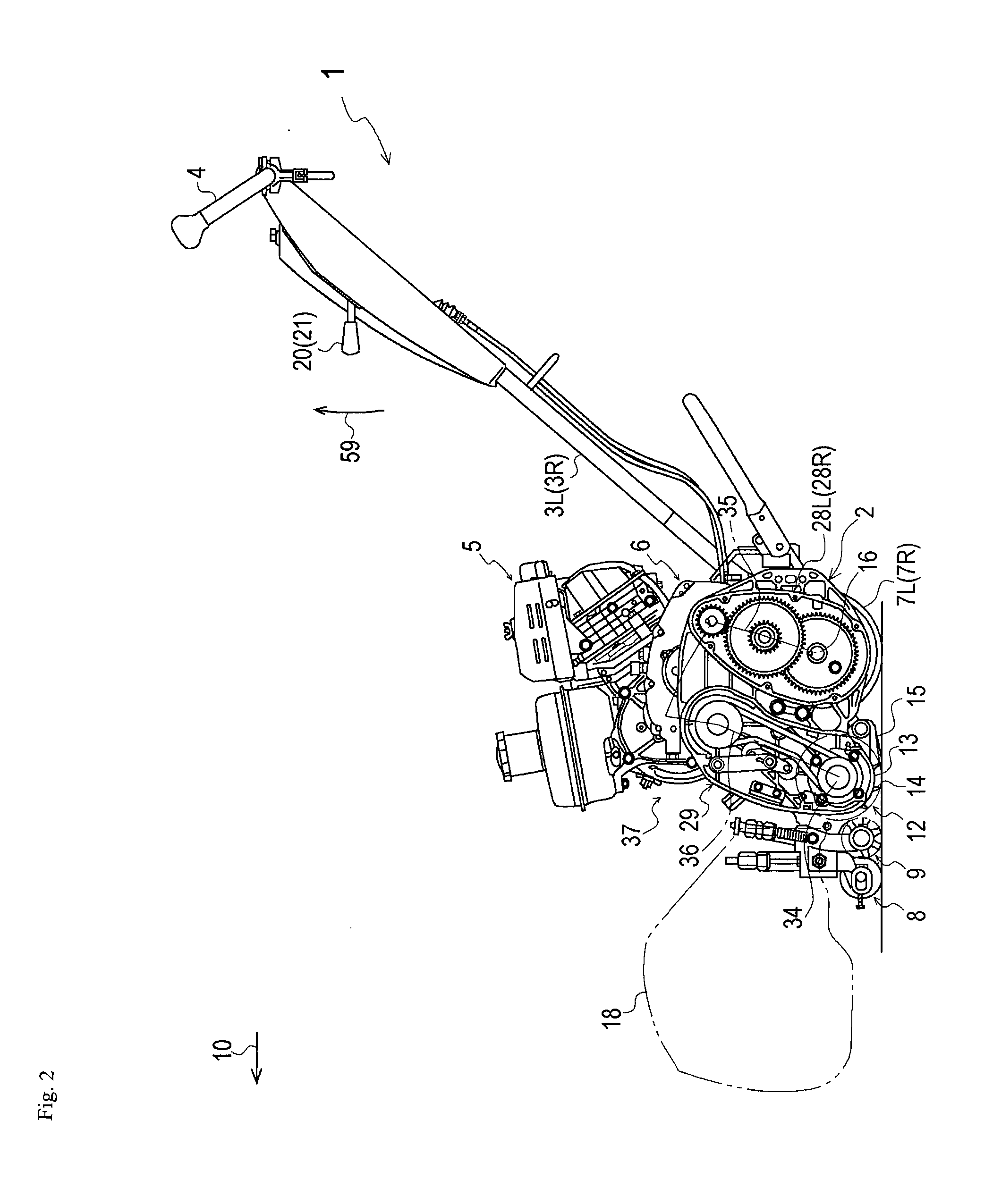
[0058]FIG. 1 is a plan view of an entire construction of a walk behind lawnmower 1 according to the present invention. FIG. 2 is a left side view of the entire construction of the walk behind lawnmower 1 according to the present invention. FIG. 3 is a planar partial cross-sectional view of a gearbox casing. FIG. 4 is a right side view of the gearbox casing illustrating a link structure for engaging or disengaging a main clutch. FIG. 5 is a perspective view of an assembly construction of a stationary cam and a movable cam. FIG. 6 is a planar partial cross-sectional view of a front portion of the gearbox casing illustrating an operation structure for a variable speed operation of a gear variable speed mechanism. FIG. 7 is a left side view of the gearbox casing whose left side is open. FIG. 8 is a left side view of a traveling transmission device whose left side is open. FIG. 9 is a back partial cross-sectional view of ...


PUM


Abstract

In a walk behind lawnmower 1 for mowing lawns that bifurcates a power from an engine 5 and transmits it to drum-type wheels 7L, 7R and a reel cutter 12, each of the first power transmission passage 35 for transmitting the power from the engine 5 to the drum-type wheels 7L, 7R and the second power transmission passage 36 for transmitting the power from the engine 5 to the reel cutter 12 has a gear variable speed mechanism 30 and an interchange mechanism 134 as speed changing structures for changing a rotating speed of each of drum shafts 16L, 16R as driving shafts.

Description

BACKGROUND OF THE INVENTION[0001]1. Field of the Invention[0002]The present invention relates to a walk behind lawnmower for mowing lawns that bifurcates a power from the engine and transmits it to drum-type wheels and a reel cutter. More specifically, the present invention relates to a power transmission mechanism for a walk behind lawnmower, which can separately change traveling speed and mowing pitch.[0003]2. Related Art[0004]Conventionally, there is well known a technology for bifurcating a power from an engine and for transmitting it to a drum-type wheels and a reel cutter, in a walk behind lawnmower for mowing lawns on a green of a golf course or the like (for example, see Patent Literature 1).[0005]Further, there is well known a technology which can change the mowing pitch, by providing a speed changing structure for changing a rotating speed of the reel cutter, at the midstream of a power transmission passage for transmitting the power from the engine to the reel cutter (for...

Claims


Application Information

Patent Timeline
IPC IPC(8): A01D69/00
CPCA01D34/56
Inventor AKAHANE, KAZUNARI
Owner IHI SHIBAURA MACHINERY CORP
Why Eureka
Try Eureka