Robot dual-joint unit as well as foot robot applying robot dual-joint unit and cooperative mechanical arm

A robot, double-joint technology, applied in manipulators, program-controlled manipulators, manufacturing tools, etc., can solve the problems of demanding wire fatigue strength, increasing moment of inertia, load and power consumption, and easily interfering with the external environment, etc. To achieve the effect of reducing the difficulty of wiring, the scheme is feasible, and the structure is simple and practical

Pending Publication Date: 2019-01-11
HZ UNITREE TECHNOLOGY CO LTD
View PDF1 Cites 10 Cited by
  • Summary
  • Abstract
  • Description
  • Claims
  • Application Information

AI Technical Summary

Problems solved by technology

[0004] 1. The first power unit needs to drive the second power unit fixed on its own output shaft to move in order to achieve external output torque. The second power unit is the load of the first power unit, so the existing joint power unit structure, This makes the first power unit increase the additional moment of inertia, load and power consumption during operation, which seriously limits the motion performance of the robot;
[0005] 2. In the application of legged robots, such as the Chinese patent application number 201720232286.5 published on March 10, 2017, a leg power system structure of an electric-driven quadruped robot, which discloses an electric-driven quadruped robot. Leg power system structure, when constructing the thigh joint and knee joint, the corresponding two power joint units of the thigh and the calf are connected in series one by one. The power unit of the thigh and the power unit of the calf are generally located in the thigh structure On both sides, when the robot moves, a part of the leg structure will protrude toward the outside of the fuselage, so the protruding part will easily interfere with the external environment; and when the robot falls, the protruding part will easily collide with the ground and cause damage. damage;
[0006] 3. In the application of legged robots, such as the Chinese patent application number 201720232286.5 published on March 10, 2017, a leg power system structure of an electric-driven quadruped robot, which discloses an electric-driven quadruped robot. Leg power system structure, when the thigh joint and knee joint are constructed, the joint power unit structure of the two power joint units corresponding to the thigh and the calf are connected in series one by one, so that when the first joint rotates, the second motor moment of the second joint is in motion with the first joint, so the routing to the second motor is very difficult and unreliable
In the prior art, using a conductive slip ring can solve the above problems, but the conductive slip ring will increase the structural complexity of the robot; if the cable is used for direct connection, very strict requirements are placed on the fatigue strength of the wire

Method used


Image

  • Robot dual-joint unit as well as foot robot applying robot dual-joint unit and cooperative mechanical arm
  • Robot dual-joint unit as well as foot robot applying robot dual-joint unit and cooperative mechanical arm
  • Robot dual-joint unit as well as foot robot applying robot dual-joint unit and cooperative mechanical arm

Examples


Embodiment Construction

[0038] Below, the present invention will be further described in conjunction with the accompanying drawings and specific implementation methods. It should be noted that, under the premise of not conflicting, the various embodiments described below or the technical features can be combined arbitrarily to form new embodiments. .

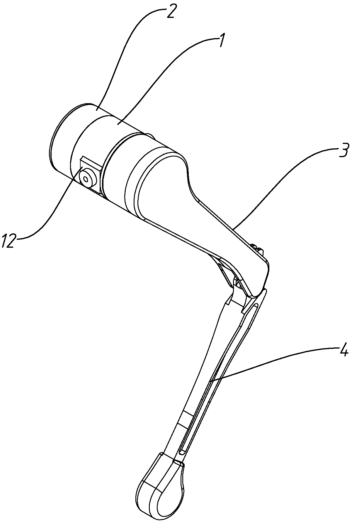
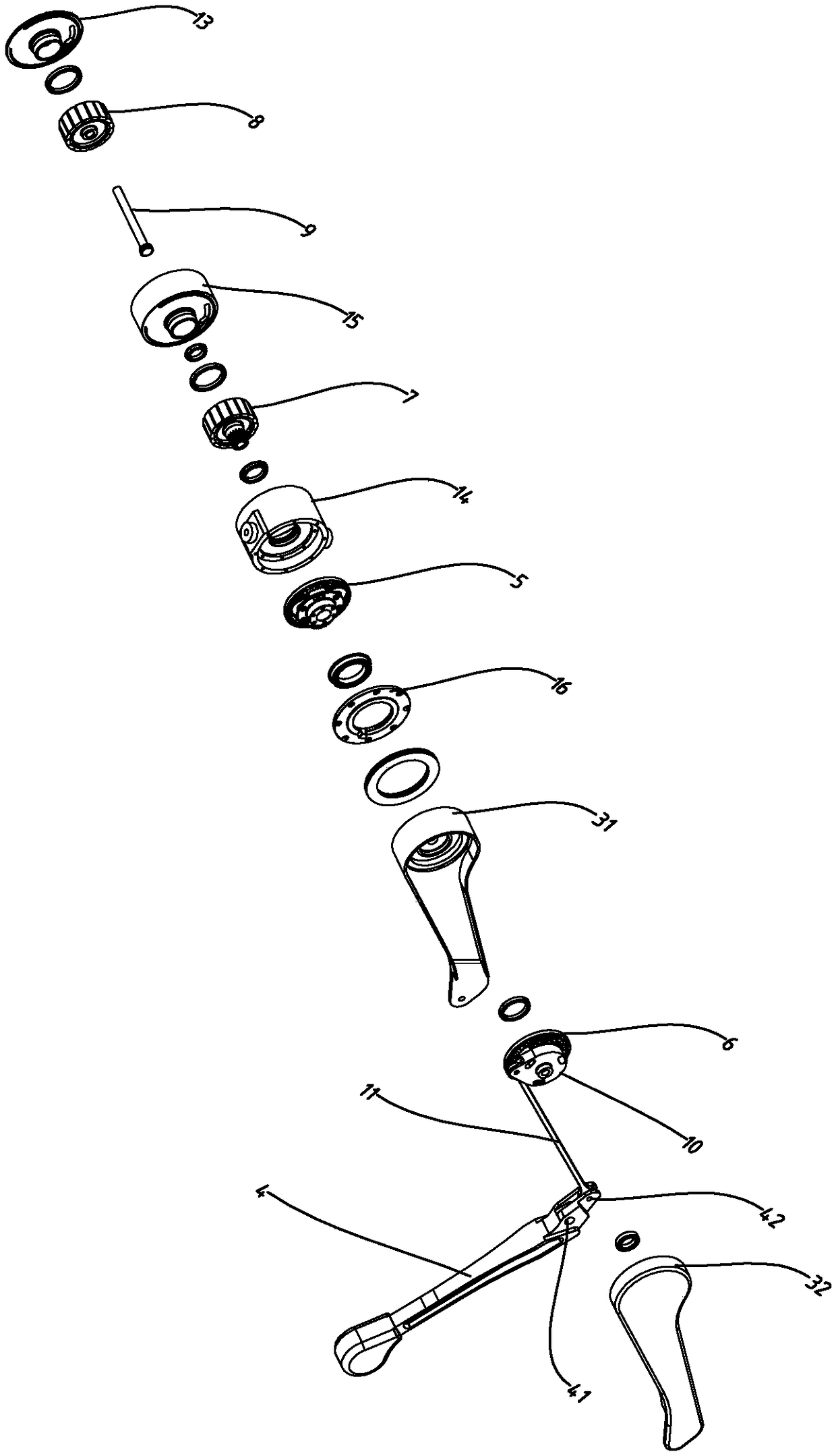
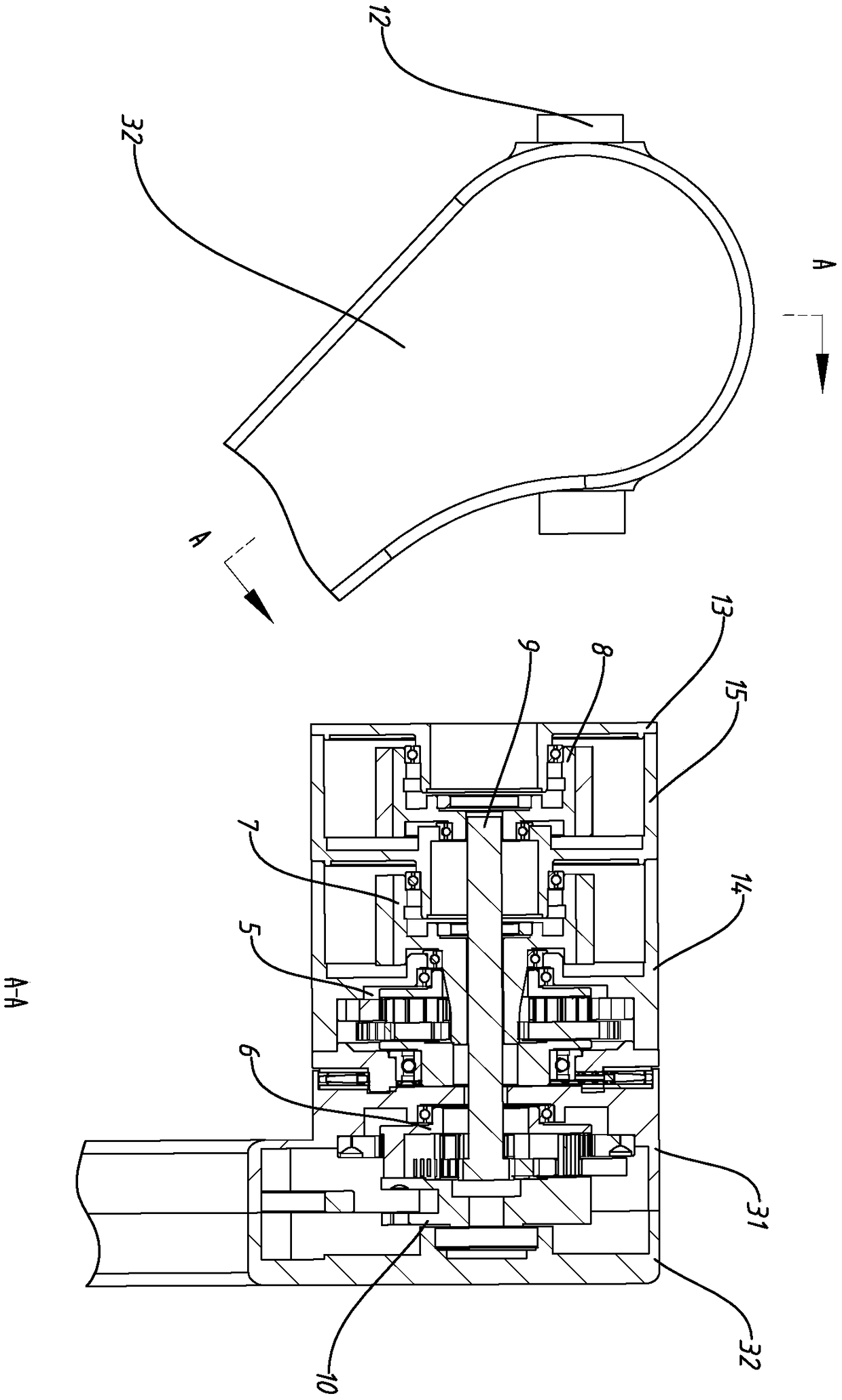
[0039] Such as figure 1 , figure 2 As shown, the highly integrated robot double-joint unit includes the first joint composed of the first motor and reducer assembly 1, the second joint composed of the second motor assembly 2 and the second reducer 6; the first motor and reducer A first output connecting rod 3 is fixed on the output shaft of the gear assembly 1 , and a second reducer 6 is arranged in the first output connecting rod 3 , and the second motor assembly 2 drives the second reducer 6 through a transmission rod 9 .

[0040] The first motor and reducer assembly 1 includes the first motor base 14, the first motor stator, the first motor rotor...


PUM


Abstract

The invention relates to the technical field of robot joints, and discloses a highly integrated robot dual-joint unit. The highly integrated robot dual-joint unit comprises a first joint which is composed of a first motor and a speed reducer assembly, and a second joint which is composed of a second motor assembly and a second speed reducer, wherein a first output connecting rod is fixedly arranged on the first motor and an output shaft of the speed reducer assembly; the second speed reducer is arranged in a first output connecting rod; and the second motor assembly drives the second speed reducer through a transmission rod. According to the robot dual-joint unit disclosed by the invention, the fixed end of the second motor assembly, the first motor and the fixed end of the speed reducer assembly are fixed together, and the fixed end of a second motor of a conventional robot joint series structure is not fixedly arranged on the first motor and the output end of the speed reducer assembly, so that output inertia of two output shafts of the robot dual-joint unit is very small; and moreover, power cables which penetrate into the second motor assembly of the second joint are cancelled.

Description

technical field [0001] The invention relates to the technical field of robot joints, in particular to a highly integrated robot double-joint unit structure. Background technique [0002] At present, whether it is a robotic arm for industrial applications or a high-performance legged robot, there are high requirements for joint power units. All hope that the joint unit has high integration, strong power, compact structure, and small output moment of inertia. At present, the existing robot joints are generally a joint power unit integrated with a single motor and a reducer, and then a legged robot or a mechanical arm adopts a combined structure of multiple joint power units connected in series one by one in practical applications. [0003] However, the existing joint power unit structure in which two power units are connected in series one by one has the following disadvantages: [0004] 1. The first power unit needs to drive the second power unit fixed on its own output sha...

Claims


Application Information

Patent Timeline
Patent Type & Authority Applications(China)
IPC IPC(8): B25J17/02
CPCB25J17/025B25J9/102B25J9/04B25J9/126B25J17/00B25J9/106B25J19/0054
Inventor 王兴兴杨知雨
Owner HZ UNITREE TECHNOLOGY CO LTD
Why Eureka
Try Eureka