A drilling device for preventing deviation of hole position and its application method for on-site installation

A technology for on-site installation and drilling devices, which is applied in the direction of drilling/drilling equipment, portable drilling rigs, metal processing equipment, etc., and can solve the problem of severe wear of protective devices, inability to guarantee drilling level, and increased operator fatigue, etc. problem, to achieve the effect of simple and fast locking operation, high integrity and increased applicability

Active Publication Date: 2020-05-19
91340100149147289C
View PDF8 Cites 0 Cited by
  • Summary
  • Abstract
  • Description
  • Claims
  • Application Information

AI Technical Summary

Problems solved by technology
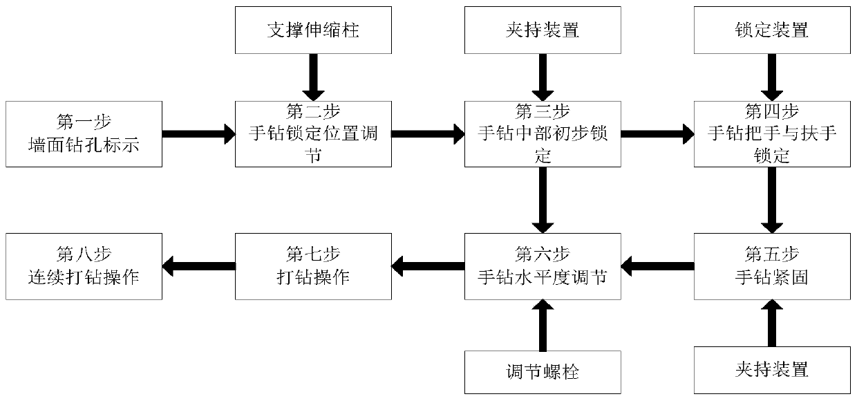
[0004] 1. The existing hand drill needs to be held manually. When the hand drill drills on the wall, the levelness of the drill hole cannot be guaranteed, and the manual holding of the hand drill will cause drilling due to hand shaking or vibration generated during drilling. Deviation of hole position;
[0005] 2. When manually holding the hand drill, the hand drill will fall due to fatigue or strong drilling vibration, which has certain safety hazards, and the body cannot use force during manual drilling, which will increase the fatigue of the operator.
[0006] For how to prevent the deviation of the drilling hole when drilling, existing patents also have some solutions. For example, the Chinese utility model patent No. 2015203835332 proposes a drilling device for drilling deviation. Buffer protection is used to prevent the drilling deviation. Due to the different diameters of the drilling holes during drilling, the drill pipe needs to be replaced frequently, so that the device needs to be equipped with different types of protection devices according to different diameters of the drill pipe. The practicability is poor, and the drilling The rod is in a state of high-speed rotation, and some drilling rigs are percussion drills, which makes the protection device wear very seriously

Method used


Image

  • A drilling device for preventing deviation of hole position and its application method for on-site installation
  • A drilling device for preventing deviation of hole position and its application method for on-site installation
  • A drilling device for preventing deviation of hole position and its application method for on-site installation

Examples


Embodiment Construction

[0044] In order to make the technical means, creative features, goals and effects achieved by the present invention easy to understand, the present invention will be further described below in conjunction with specific illustrations. It should be noted that, in the case of no conflict, the embodiments in the present application and the features in the embodiments can be combined with each other.

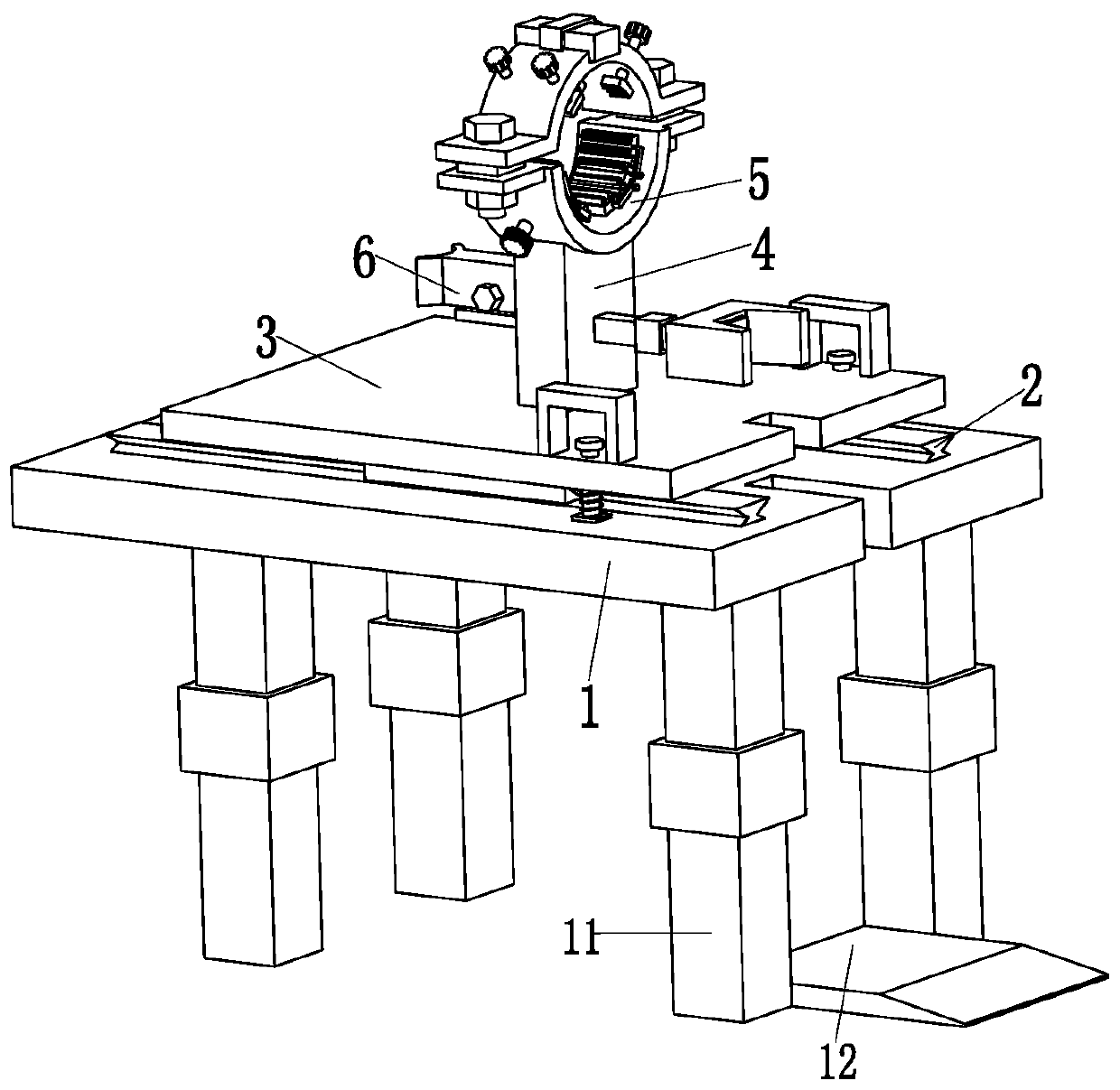
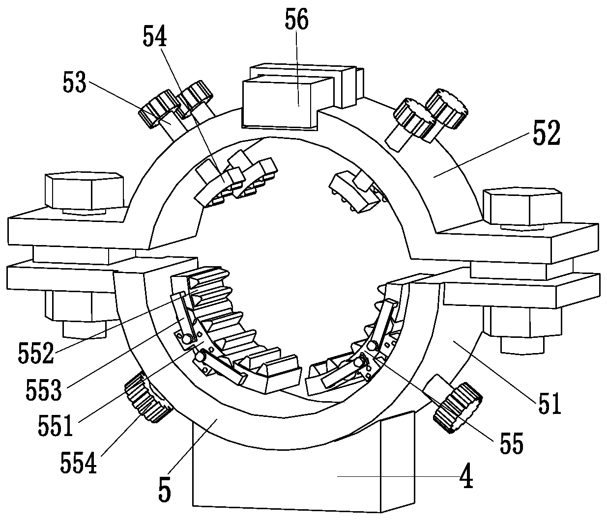
[0045] Such as Figure 1 to Figure 7 As shown, a drilling device for preventing deviation of the hole position for on-site installation includes a support plate 1, a slide rail 2, a sliding plate 3, a connecting column 4, a clamping device 5 and a locking device 6, and the support plate The slide rail 2 is installed on the top of 1, the slide plate 3 is installed on the slide rail 2 by sliding fit, the connecting column 4 is installed on the upper end surface of the middle part of the slide plate 3, and the clamping device 5 is installed on the top of the connecting column 4 On the ...


PUM


Abstract

The invention relates to a drilling device used for field mounting and hole site deviation prevention and an application method of the drilling device. The drilling device comprises a support plate, sliding rails, a sliding plate, a connecting column, a clamping device and a locking device. The sliding rails are mounted at the top of the support plate. The sliding plate is mounted on the sliding rails in a sliding fit manner. The connecting column is mounted on the upper end face of the middle of the sliding plate. The clamping device is mounted at the top of the connecting column. The lockingdevice is mounted on the side face of the connecting column. The clamping device comprises a supporting clamping jaw, a locking clamping jaw, adjusting bolts, adjusting clamp blocks and supporting mechanisms. The locking device comprises a locking body, a locking clamp plate, a locking telescopic column and a tight supporting clamp block. The problems that when an existing hand drill carries drilling operation on a wall, drilling levelness cannot be guaranteed, drilling position deviation is prone to being caused during manual drilling, and the hand drill falls off due to fatigue or high drilling vibration force when the hand drill is manually held can be solved.

Description

technical field [0001] The invention relates to the technical field of home decoration construction, in particular to a drilling device for preventing deviation of hole positions for on-site installation and a use method thereof. Background technique [0002] Home decoration construction often requires drilling on the wall. Most of these drilling holes are flat holes. During drilling construction, it is generally carried out by manually holding a hand drill. During manual drilling construction, hand shaking often causes The drilling is skewed or the drilling has a certain inclination angle. When there is a problem with the drilling, it is necessary to re-drill the drilling. This will have a certain impact on the beauty of the wall and affect the position of the object installed on the drilling. [0003] The specific problems that exist when the existing manual drilling is carried out on the wall surface are as follows: [0004] 1. The existing hand drill needs to be held ma...

Claims


Application Information

Patent Timeline
Patent Type & Authority Patents(China)
IPC IPC(8): B23B45/14
CPCB25H1/0021
Inventor 吴银国俞宏波
Owner 91340100149147289C
Why Eureka
Try Eureka