

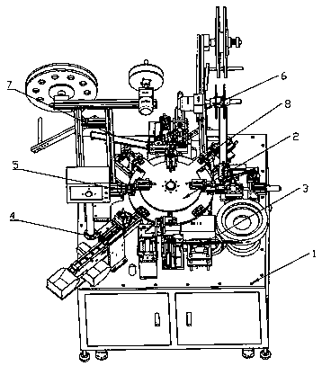
Full-automatic connector assembling machine
A connector group, fully automatic technology, applied in the direction of assembly machines, metal processing equipment, metal processing, etc., can solve the problems of not being able to keep up with customer needs, low production efficiency, high cost, etc., to save equipment space and processing equipment The effect of investment, saving production cost and labor cost input, and good market application value
- Summary
- Abstract
- Description
- Claims
- Application Information
AI Technical Summary
Problems solved by technology
Method used
Image

Examples
Embodiment 2
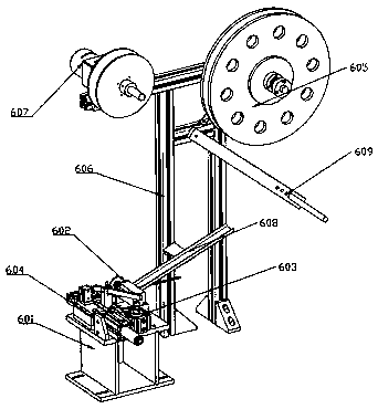
[0035] Embodiment 2 is different from the above in that the feeding unit 602 includes a feeding table, a feeding motor 607, a feeding divider and a feeding fixing plate, the feeding table is fixed on the PIN fixing frame 601, and the feeding motor The fixed end of 607 is vertically installed on one side of the dividing plate, and the dividing plate is vertically fixed on the left side of the feeding table, and the output end of the feeding motor 607 passes through the dividing plate vertically to connect to the feeding divider on the other side of the dividing plate, A feeding groove is arranged in the middle of the feeding table, a feeding fixing plate is arranged on the upper surface of the feeding table, and the feeding divider is arranged above the feeding groove.
Embodiment 3
[0036] Embodiment 3 is different from the above in that the cutting unit 603 includes a cutting motor, a cutting rod, a cutting column, a cutting table and a cutter, and the cutting table is arranged in parallel with the feeding table, so The cutting column is arranged on the rear side of the cutting table, the cutting rod is vertically installed on the top of the cutting column, one end of the cutting rod is connected to the cutter, and the other end of the cutting rod is connected to the cutting rod. At the output end of the motor, the cutter is set on the cutting table, a cutting track is set in the middle of the cutting table, and the fixed end of the cutting motor is fixedly installed on the PIN fixing frame 601 .
Embodiment 4
[0037] Embodiment 4 differs from the above in that the installation unit 604 includes an installation motor, an installation push block, an installation table and an installer, the installation table is arranged in parallel with the cutting table, and the middle part of the installation table is provided with an installation dislocation slot, the installer output end is set above the installation dislocation slot, the fixed end of the installer is fixedly installed on the turntable, the installation motor is fixedly installed on the PIN fixing frame 601, and the installation The output end of the motor is connected to the installer through the installation push block.
PUM
 Abstract
Description
Claims
Application Information