Hydraulic oil cylinder piston rod adjusting device

A technology for adjusting devices and hydraulic cylinders, applied in the direction of fluid pressure actuating devices, etc., can solve the problems of unilateral wear of seals and guide elements, oil leakage of hydraulic cylinders, etc., and achieve the effect of avoiding unilateral wear

Pending Publication Date: 2019-08-20
GUANGZHOU HUAYAN PRECISION MACHINERY
View PDF0 Cites 0 Cited by
  • Summary
  • Abstract
  • Description
  • Claims
  • Application Information

AI Technical Summary

Problems solved by technology

[0002] In hydraulic cylinder transmission technology, when the oil cylinder is placed horizontally, if one end of the piston rod is suspended, the piston rod will sag due to its own weight, causing unilateral wear of the seal and guide elements, resulting in oil leakage from the hydraulic cylinder

Method used


Image

  • Hydraulic oil cylinder piston rod adjusting device
  • Hydraulic oil cylinder piston rod adjusting device
  • Hydraulic oil cylinder piston rod adjusting device

Examples


Embodiment 1

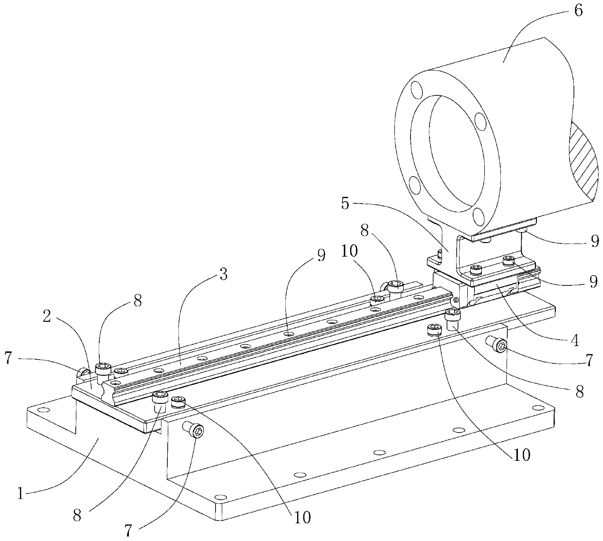
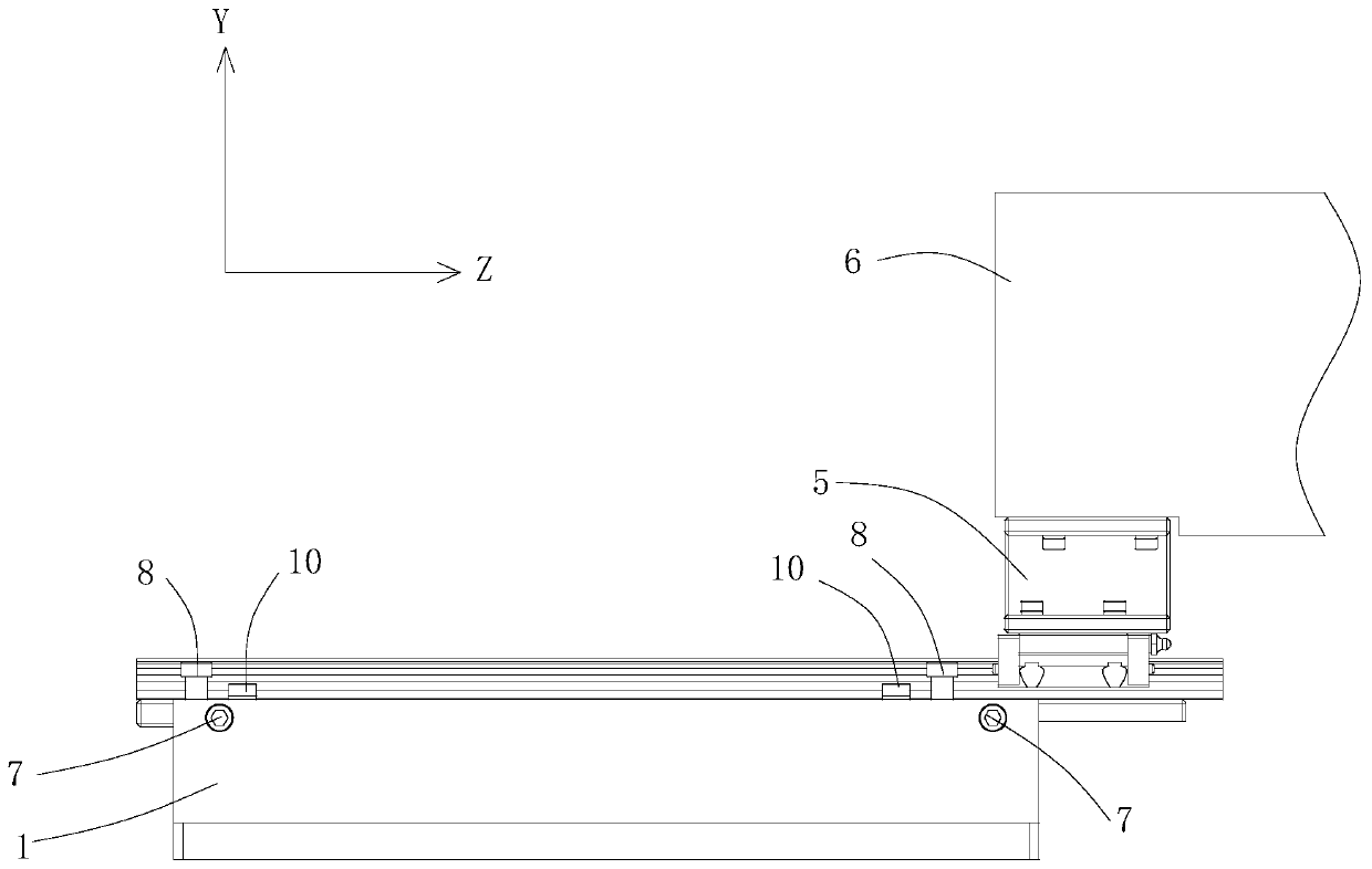
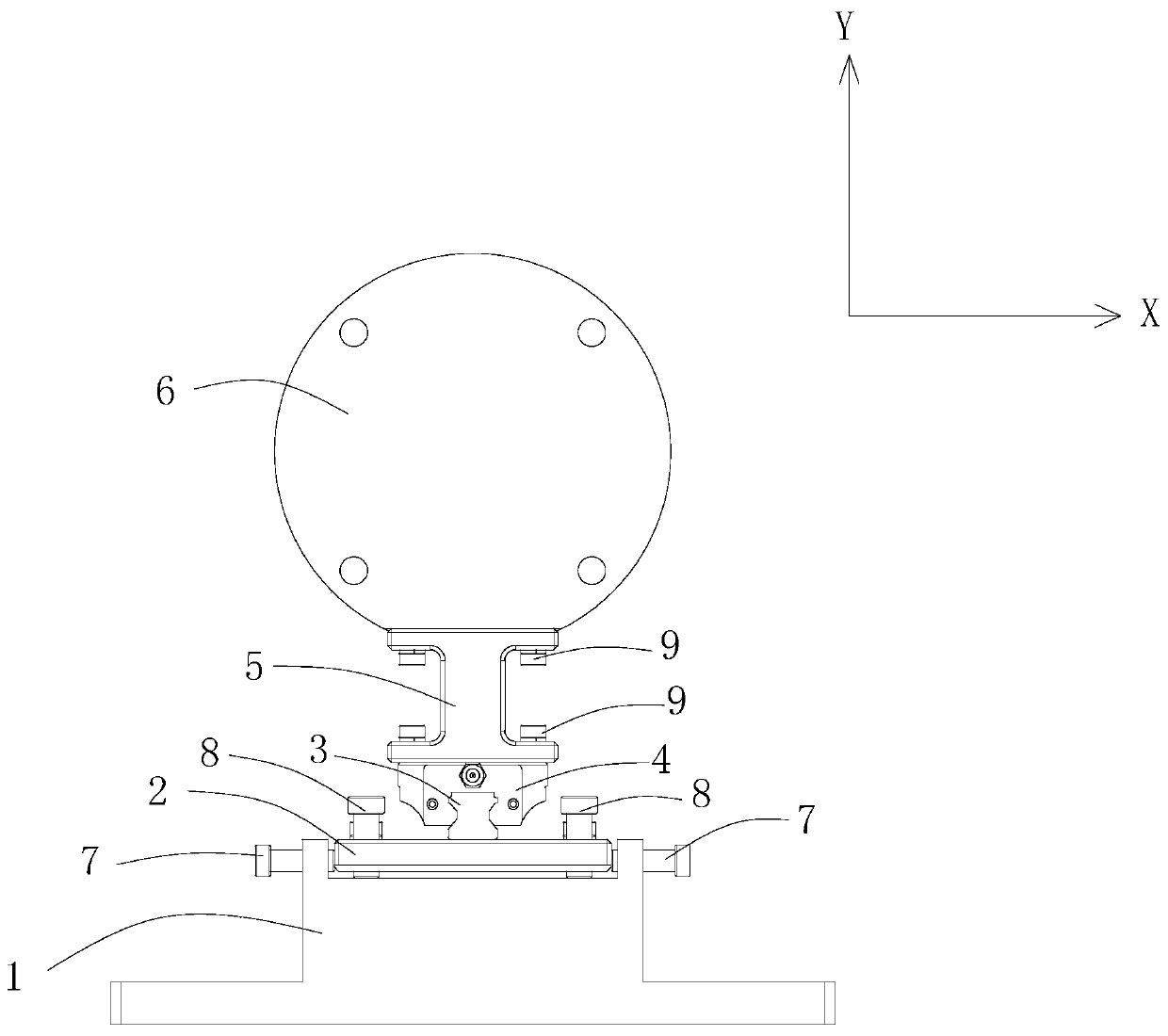
[0023] Embodiment 1: as Figure 1-3 The hydraulic cylinder piston rod adjustment device shown is placed directly below the free end of the piston rod 6 of the hydraulic cylinder. There is a boss, and an adjustment groove is opened on the boss, the adjustment plate 2 is embedded in the adjustment groove, the guide rail 3 is set on the adjustment plate 2, the support seat 5 is slidingly connected with the guide rail 3, and the support seat 5 can slide along the guide rail. The extension direction of 3 moves, the support seat 5 is used to connect with the piston rod 6, the adjustment assembly is respectively connected with the fixed seat 1 and the adjustment plate 2, and the adjustment assembly adjusts the position of the adjustment plate 2 in the adjustment groove, so that the support seat 5 and the adjustment plate The contact surface of the piston rod 6 is in a horizontal position, and the support seat 5 fixes the piston rod 6 and makes it in a horizontal position.

[0024] A...

Embodiment 2

[0034] Embodiment 2: as Figure 1-3 The hydraulic cylinder piston rod adjustment device shown is placed directly below the free end of the piston rod 6 of the hydraulic cylinder. There is a boss, and an adjustment groove is opened on the boss, the adjustment plate 2 is embedded in the adjustment groove, the guide rail 3 is set on the adjustment plate 2, the support seat 5 is slidingly connected with the guide rail 3, and the support seat 5 can slide along the guide rail. The extension direction of 3 moves, the support seat 5 is used to connect with the piston rod 6, the adjustment assembly is respectively connected with the fixed seat 1 and the adjustment plate 2, and the adjustment assembly adjusts the position of the adjustment plate 2 in the adjustment groove, so that the support seat 5 and the adjustment plate The contact surface of the piston rod 6 is in a horizontal position, and the support seat 5 fixes the piston rod 6 and makes it in a horizontal position.

[0035] A...

Embodiment 3

[0046] Embodiment 3: as Figure 1-3 The hydraulic cylinder piston rod adjustment device shown is placed directly below the free end of the piston rod 6 of the hydraulic cylinder. There is a boss, and an adjustment groove is opened on the boss, the adjustment plate 2 is embedded in the adjustment groove, the guide rail 3 is set on the adjustment plate 2, the support seat 5 is slidingly connected with the guide rail 3, and the support seat 5 can slide along the guide rail. The extension direction of 3 moves, the support seat 5 is used to connect with the piston rod 6, the adjustment assembly is respectively connected with the fixed seat 1 and the adjustment plate 2, and the adjustment assembly adjusts the position of the adjustment plate 2 in the adjustment groove, so that the support seat 5 and the adjustment plate The contact surface of the piston rod 6 is in a horizontal position, and the support seat 5 fixes the piston rod 6 and makes it in a horizontal position.

[0047] A...


PUM


Abstract

The invention discloses a hydraulic oil cylinder piston rod adjusting device. The hydraulic oil cylinder piston rod adjusting device comprises a fixing seat, an adjusting plate, a guide rail, a supporting seat and an adjusting assembly, wherein an adjusting groove is formed in the fixing seat, the adjusting plate is arranged on the adjusting groove, the guide rail is arranged on the adjusting plate, the supporting seat is in sliding connection with the guide rail, the supporting seat can move in the extending direction of the guide rail, and the supporting seat is used for being connected witha piston rod; the adjusting assembly is movably connected with the fixing seat and the adjusting plate respectively, the adjusting assembly adjusts the position of the adjusting plate in the adjusting groove, so that the contact surface of the supporting seat and the piston rod is in a horizontal position, and the supporting seat fixes the piston rod and enables the piston rod to be in a horizontal position. According to the hydraulic oil cylinder piston rod adjusting device, and the piston rod of the hydraulic cylinder can be always in the horizontal position, and the oil leakage of the hydraulic cylinder caused by the unilateral abrasion of a sealing part due to the fact that the piston rod is drooping due to self-weight is avoided.

Description

technical field [0001] The invention relates to a hydraulic transmission technology, in particular to a hydraulic oil cylinder piston rod adjustment device. Background technique [0002] In the hydraulic cylinder transmission technology, when the cylinder is placed horizontally, if one end of the piston rod is suspended in the air, the piston rod will sag due to its own weight, causing unilateral wear of the seal and guide elements, resulting in oil leakage from the hydraulic cylinder. Contents of the invention [0003] In order to overcome the deficiencies of the prior art, the object of the present invention is to provide a hydraulic cylinder piston rod adjustment device, which can keep the hydraulic cylinder piston rod in a horizontal position all the time, avoiding the hydraulic pressure caused by the unilateral wear of the seal caused by the piston rod drooping due to its own weight. The cylinder is leaking oil. [0004] The purpose of the present invention adopts fo...

Claims


Application Information

Patent Timeline
IPC IPC(8): F15B15/20
CPCF15B15/20
Inventor 卢敏刘伟波
Owner GUANGZHOU HUAYAN PRECISION MACHINERY
Why Eureka
Try Eureka