Front wiring system for wall switch socket

A wiring system and wall switch technology, applied in the direction of electric switch, connection, conductive connection, etc., can solve problems such as wire falling off, contact parts are easily damaged, and wires and terminal blocks are in poor contact, so as to reduce the difficulty of installation and operation and make the contact firm tight, security-increasing effect

Inactive Publication Date: 2019-08-20
LIANG PING
View PDF3 Cites 3 Cited by
  • Summary
  • Abstract
  • Description
  • Claims
  • Application Information

AI Technical Summary

Problems solved by technology

There are too many wires connected to the switch socket. When the functional panel is installed back on the wall bottom box, it needs to be pressed with a lot of pressure to install and position, which will easily cause two hidden dangers. One is that the installed contacts are easily damaged, especially the wall bottom box Second, when pressing down for installation and positioning, due to the physical properties of the wire such as elasticity and hardness, the contact stress between the wire and the terminal block will be redistributed, which will easily cause poor contact between the wire and the terminal block, and even cause Faults such as wire falling off
[0003] The research on the access mode of switches and sockets is currently mainly focused on the rapid assembly and replacement of panels or functional connectors, such as "A Wall Switch, Socket, and Switch Socket for Easy Maintenance and Replacement" (application number 201110058099.7), "One A Quick-Change Wall Switch, Socket, Switch Socket" (Patent No. 201110436971. 7), "An Adjustable Multi-function Switch Socket Box" (Application No. The rapid replacement and maintenance of connectors provides people with more and better choices, which facilitates life, but the wiring method between the wires drawn from the wall bottom box and the switch socket panel has not been studied

Method used


Image

  • Front wiring system for wall switch socket
  • Front wiring system for wall switch socket
  • Front wiring system for wall switch socket

Examples


Embodiment Construction

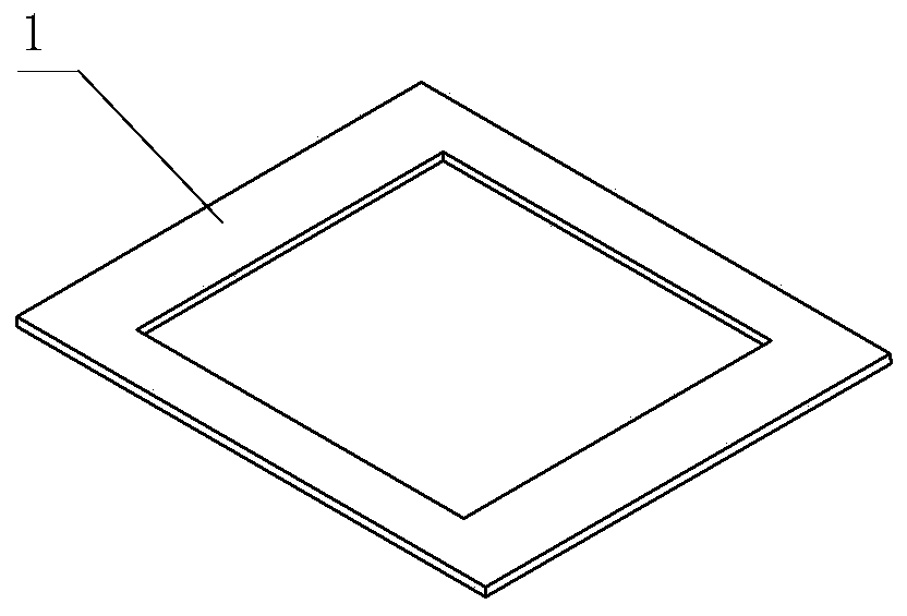
[0020] figure 1 It is a schematic diagram of the cover plate 1. After the panel 2 is assembled, cover it on the panel 2 and fix it to cover the functional connection holes, fixing screws, connecting screws, etc. on the panel 2, mainly for the protection of the panel, aesthetics and insulation. . In the schematic diagram, the cover plate 1 is a hollowed-out square. In actual design and use, it should be designed according to the actual needs of the panel 2. It cannot be square in the schematic diagram, and it is inferred that the cover plate 1 is only a square hollowed out structure.

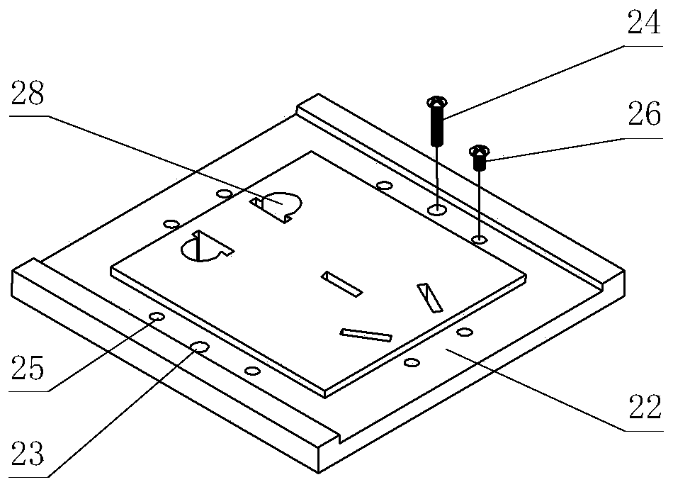
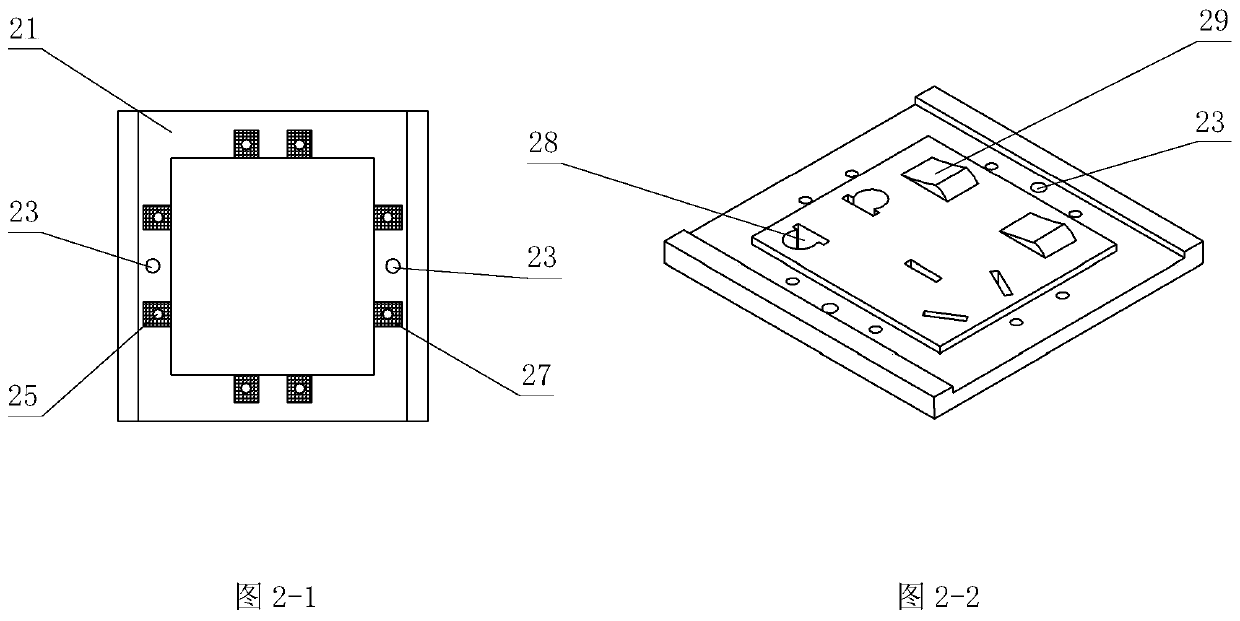
[0021] figure 2 It is a schematic diagram of panel 2, which is a five-hole socket panel, which is only used as a demonstration for applying for this patent. In actual use, the manufacturer installs different functional parts on the panel according to the needs, mainly including the jack function part 28 and the switch function part 29, to meet various use needs, so the panel is various in appe...


PUM


Abstract

A front wiring system for a wall switch socket is characterized in that a wiring part of the switch socket is changed to be connected to a wiring seat of a wiring bracket with a hollow middle part from a wiring seat on the back surface of an original switch socket panel, and then an open head socket panel and a cover plate are mounted. The transmission path of an access power supply is as follows:a wire-a wiring head on the wiring bracket-a lower metal contact piece on the wiring bracket-an upper metal contact piece on the back surface of the panel- a head or jack function piece on the panel.Through the improvement, the operation is more convenient, the disturbance to the wiring part is avoided in the whole wiring process and the installation process of the head socket panel and the cover plate, and the wiring is more stable and reliable.

Description

technical field [0001] The invention relates to the technical field of wall switch sockets, in particular to the wiring method of wall switch socket wires, which is changed from the traditional rear connection to the front connection, so that the connection between the wires and the terminal blocks is more convenient and the contact is firmer. Background technique [0002] The traditional switch socket is equipped with a plurality of terminal blocks on the back of the switch socket functional panel, and the power line, control line, and signal line drawn from the wall bottom box (for the convenience of statement, the power line, control line, The signal lines are collectively referred to as wires), plugged into the jacks of the above-mentioned terminal blocks, tighten the screws, and then press down the functional panel to install it on the wall bottom box. Generally, a five-hole socket needs to be connected to 3 wires, a five-hole switch socket needs to be connected to 5 wi...

Claims


Application Information

Patent Timeline
Patent Type & Authority Applications(China)
IPC IPC(8): H01R24/76H01R13/00H01R13/502H01R13/516H01R9/24H01H1/58H01H9/00
CPCH01H1/58H01H9/00H01R9/2433H01R9/2491H01R13/00H01R13/502H01R13/516H01R24/76
Inventor 不公告发明人
Owner LIANG PING
Why Eureka
Try Eureka