Novel braking vacuum tank mounting device and automobile

A technology for installing devices and vacuum tanks, which is applied in the automotive field, can solve problems such as unreasonable cabin space occupation, and achieve the effects of solving cabin space congestion, saving settings, and reducing costs

Pending Publication Date: 2019-08-23
LAUNCH DESIGN INC LTD
View PDF0 Cites 0 Cited by
  • Summary
  • Abstract
  • Description
  • Claims
  • Application Information

AI Technical Summary

Problems solved by technology

However, the brake vacuum tank is arranged in the engine room, which occupies an unreasonable amount of space in the already crowded engine room, and even cannot be arranged in many cases.

Method used


Image

  • Novel braking vacuum tank mounting device and automobile

Examples


Embodiment 1

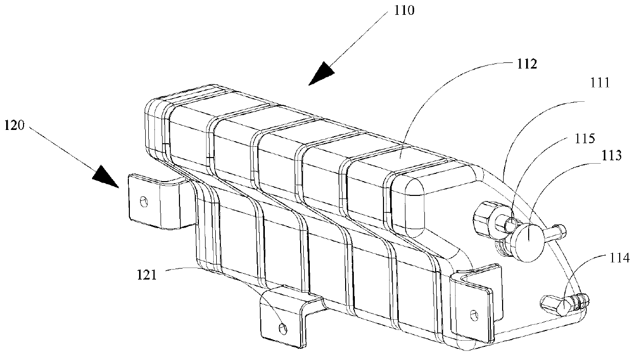
[0028] see figure 1 , this embodiment 1 provides a new brake vacuum tank 110 installation device. The installation device of the novel brake vacuum tank 110 includes: a vacuum tank 110 and a plurality of fixing parts 120; the vacuum tank 110 is fixed between the vehicle body sheet metal and the fender through the plurality of fixing parts 120. By placing the vacuum tank 110 between the fender and the sheet metal of the vehicle body, the problem of crowded space in the engine room is solved, and at the same time, the setting of the installation bracket of the vehicle body is saved, and the cost is reduced.

[0029] In this embodiment, the vacuum tank 110 is surrounded by fan-shaped side walls 111 and four rectangular side walls 112; and two of the rectangular side walls 112 are arranged vertically, and the other two rectangular side walls 112 are arranged at acute angles; And one of the two vertical rectangular side walls 112 is set at an obtuse angle with one of the two acute...


PUM


Abstract

The invention relates to a novel braking vacuum tank mounting device. The novel braking vacuum tank mounting device comprises a vacuum tank and multiple fixing pieces; and the vacuum tank is fixed between a vehicle body metal plate and a fender through the multiple fixing pieces. By placing the vacuum tank between the fender and the vehicle body metal plate, a problem that an engine compartment space is crowded is solved, and meanwhile, the arranging of a vehicle body mounting bracket is avoided, and the cost is reduced.

Description

technical field [0001] The invention relates to the field of automobiles, in particular to a novel brake vacuum tank installation device and an automobile. Background technique [0002] With the development of society, cars are more and more widely used in daily life and work. The current car often uses a vacuum tank, which is a device on the car that is responsible for storing the vacuum drawn by the electric vacuum pump, collecting vacuum degree signals, and controlling the direction of the vacuum. At present, most cars arrange the vacuum tanks in the cabin, which makes the already crowded cabin space more crowded and messy, and even the vacuum booster tank cannot be arranged in the cabin in many cases. [0003] It is now conventional to place the brake vacuum canister in the engine room and use a bracket to mount it. However, the brake vacuum tank is arranged in the cabin, which takes up unreasonable space in the already crowded cabin, and even often cannot be arranged....

Claims


Application Information

Patent Timeline
IPC IPC(8): B60T17/06
CPCB60T17/06
Inventor 陈磊赵彬
Owner LAUNCH DESIGN INC LTD
Why Eureka
Try Eureka