Traction beam structure, end chassis with traction beam structure and rail vehicle

A traction beam and structure technology, applied in the field of rail vehicles, can solve the problems of poor welding quality, uneven heat input, and easy deformation.

Active Publication Date: 2019-08-23
CRRC QINGDAO SIFANG CO LTD
View PDF7 Cites 9 Cited by
  • Summary
  • Abstract
  • Description
  • Claims
  • Application Information

AI Technical Summary

Problems solved by technology

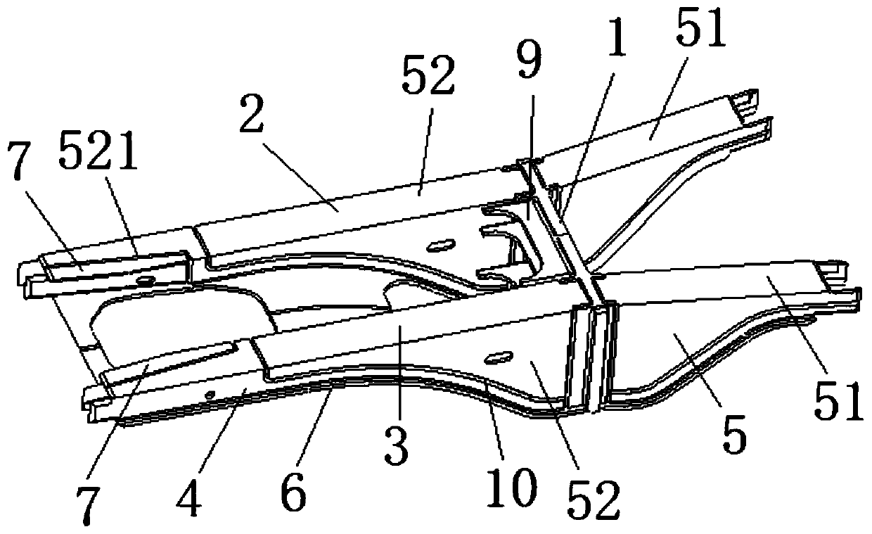
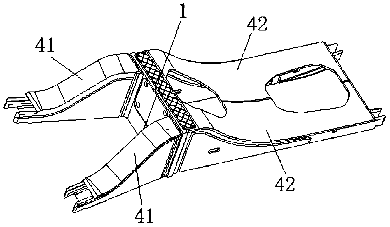
[0007] The object of the present invention is to provide a drawbeam structure, an end chassis with the structure and a rail vehicle, to at least solve the problem that the drawbeam structure in the prior art usually adopts manual arc welding, which easily leads to uneven heat input, One of the technical problems of poor welding quality and easy deformation after welding

Method used


Image

  • Traction beam structure, end chassis with traction beam structure and rail vehicle
  • Traction beam structure, end chassis with traction beam structure and rail vehicle
  • Traction beam structure, end chassis with traction beam structure and rail vehicle

Examples


Embodiment Construction

[0030] The specific implementation manners of the present invention will be further described in detail below in conjunction with the accompanying drawings and embodiments. The following examples are used to illustrate the present invention, but are not intended to limit the scope of the present invention.

[0031] In the description of the present invention, it should be noted that unless otherwise specified and limited, the terms "installation", "connection" and "connection" should be understood in a broad sense, for example, it can be a fixed connection or a detachable connection. Connected, or integrally connected; it may be mechanically connected or electrically connected; it may be directly connected or indirectly connected through an intermediary, and it may be the internal communication of two components. Those of ordinary skill in the art can understand the specific meanings of the above terms in the present invention in specific situations.

[0032] Such as Figure...


PUM


Abstract

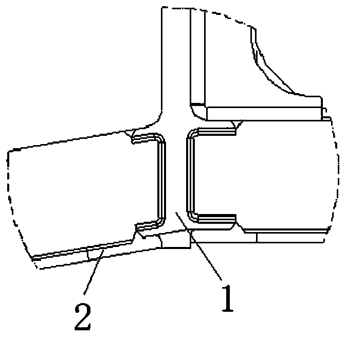
The invention relates to the technical field of rail vehicles, and discloses a traction beam structure, an end chassis with the traction beam structure and a rail vehicle. The traction beam structurecomprises a coupler mounting seat, a first traction beam body and a second traction beam body, wherein the first traction beam body and the second traction beam body are oppositely arranged and are arranged on the two sides of the coupler mounting seat correspondingly, the first traction beam body and the second traction beam body both comprise lower cover plates and traction beam web plates whichare arranged at the upper ends of the lower cover plates and are in butt joint with the lower cover plates, V-shaped grooves are formed in the butt joint positions of the lower cover plates and the traction beam web plates, and the edges of the traction beam web plates protrude out of the edges of the lower cover plates to form mounting parts. The traction beam structure has the advantages of being capable of realizing automatic welding, good in welding quality and small in deformation after welding.

Description

technical field [0001] The invention relates to the technical field of rail vehicles, in particular to a traction beam structure, an end chassis with the structure and a rail vehicle. Background technique [0002] The traction beam structure of the car body underframe is the key force transmission part in the process of traction and braking of the car body. And the transmission of the traction force of the traction pin. At the same time, during the braking process of the vehicle, the traction beam structure will bear the compressive load. The traction beam structure is an important component of the chassis to realize the longitudinal force transmission during the vehicle operation. [0003] The connection method between the coupler mounting seat and the drawing beam in the existing drawing beam structure is as follows: the hot riveting structure is used to realize the fixed connection between the coupling mounting seat and the web of the drawing beam, and the material of the...

Claims


Application Information

Patent Timeline
Patent Type & Authority Applications(China)
IPC IPC(8): B61F1/10B61F1/14
CPCB61F1/10B61F1/14
Inventor 张成功尚克明刘龙玺林鹏刘命鹏
Owner CRRC QINGDAO SIFANG CO LTD
Why Eureka
Try Eureka