Mounting structure of clutch separation shifting fork and supporting mechanism

A technology for separating shift forks and supporting mechanisms, which is applied in the direction of clutches, mechanical drive clutches, couplings, etc., can solve the problems of clutch pedal vibration, abnormal noise of separation shift forks, etc., and achieve the effects of avoiding shaking, convenient installation, and ingenious design

Inactive Publication Date: 2016-08-10
CHONGQING KAITE POWER SCI & TECH
View PDF6 Cites 0 Cited by
  • Summary
  • Abstract
  • Description
  • Claims
  • Application Information

AI Technical Summary

Problems solved by technology

The existing problems are: (1) When the clutch release fork is installed on the clutch housing through the support mechanism, the degree of freedom in only one direction is restricted. Under the excitation of the clutch, the release fork can move and swing radially, so It is easy to produce abnormal noise of the separation fork and vibration of the clutch pedal; (2) due to the natural frequency of the clutch separation fork itself, it is easy to coincide with the natural frequency of the engine during the change of engine speed, resulting in resonance and vibration of the clutch pedal

Method used


Image

  • Mounting structure of clutch separation shifting fork and supporting mechanism
  • Mounting structure of clutch separation shifting fork and supporting mechanism
  • Mounting structure of clutch separation shifting fork and supporting mechanism

Examples


Embodiment Construction

[0014] Below by embodiment and in conjunction with accompanying drawing, the present invention will be further described:

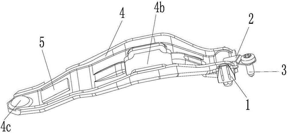
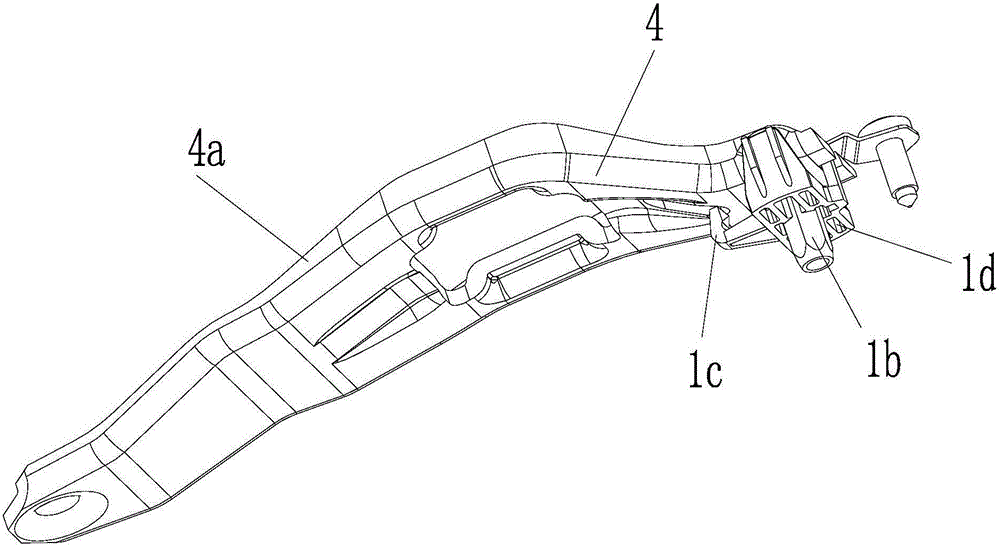
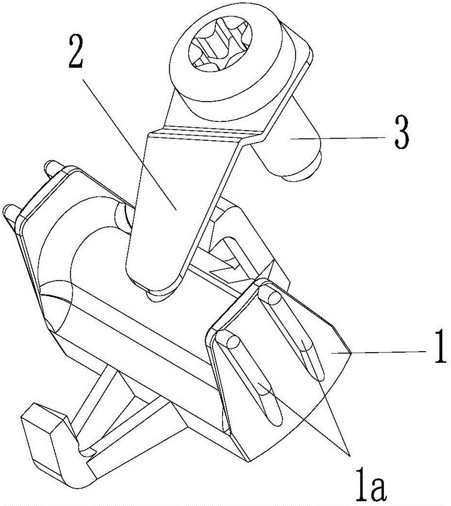
[0015] to combine figure 1 — image 3 As shown, an installation structure of a clutch release fork and a support mechanism is mainly composed of a clutch release fork 4 and a support mechanism.

[0016] The clutch release shift fork 4 is an integrally formed plate-shaped metal sheet. Preferably, the metal sheet is symmetrical left and right as a whole. The middle part of the metal sheet is wide, and the width towards the front and rear ends gradually decreases. Flanged 4a for added strength. The rear end of the metal sheet is provided with an upwardly arched circular pit 4c as the contact point of the clutch actuator, and the middle part of the metal sheet is provided with a rectangular hole 4b for installing the release bearing.

[0017] A mass block 5 is welded on the top surface of the clutch release shift fork 4, and the mass block 5 is welded in t...


PUM


Abstract

The invention discloses a mounting structure of a clutch separation shifting fork and a supporting mechanism. A mass block is welded to the top face of the separation shifting fork. The supporting mechanism comprises a rubber mounting base, an elastic press piece and a locking bolt. A U-shaped base serves as a body of the rubber mounting base. An inserting column extending downwards is arranged at the bottom of the U-shaped base. A sheet metal part with the middle portion bent and the front portion and the rear portion parallel serves as the elastic press piece, and the locking bolt is sleeved with the front portion of the elastic press piece. The front end of the clutch separation shifting fork is clamped in a U-shaped opening of the rubber mounting base from top to bottom. A hook head of the rubber mounting base is hooked in a via hole correspondingly formed in the clutch separation shifting fork. The rear portion of the elastic press piece is pressed on the front end of the clutch separation shifting fork. The radial movement and rotation freedom degree of the shifting fork can be restrained, and pedal shaking and separation shifting fork abnormal sounds brought by clutch excitation can be absorbed well; and modals are increased to change the inherent frequency of the separation shifting fork, and the situation that resonance is caused by inherent frequency coincidence of engines is avoided.

Description

technical field [0001] The invention relates to the technical field of automobile engine parts, in particular to an installation structure of a clutch release shift fork and a support mechanism. Background technique [0002] One end of the clutch release fork is installed on the clutch housing through the support mechanism, and the other end is provided with an upwardly arched pit as the contact point of the clutch actuator, and a rectangular hole is provided in the middle for installing the release bearing. The existing problems are: (1) When the clutch release fork is installed on the clutch housing through the support mechanism, the degree of freedom in only one direction is restricted. Under the excitation of the clutch, the release fork can move and swing radially, so It is easy to produce abnormal noise of the separation fork and vibration of the clutch pedal; (2) due to the natural frequency of the clutch separation fork itself, it is easy to coincide with the natural...

Claims


Application Information

Patent Timeline
Patent Type & Authority Applications(China)
IPC IPC(8): F16D23/12F16F15/08F16F15/22
CPCF16D23/12F16D2300/12F16D2300/22F16F15/08F16F15/223F16F2222/08
Inventor 白天明延虎和燕萍邓华
Owner CHONGQING KAITE POWER SCI & TECH
Why Eureka
Try Eureka