
Calibration method and device for an optical fiber strain sensing system

A technology of optical fiber strain and sensing system, which is applied in the direction of measuring devices, electrical devices, instruments, etc., to achieve the effect of simple operation, ensuring rationality and feasibility, and improving accuracy

Active Publication Date: 2020-05-26
UNIV OF ELECTRONICS SCI & TECH OF CHINA
View PDF5 Cites 0 Cited by
  • Summary
  • Abstract
  • Description
  • Claims
  • Application Information

AI Technical Summary

Problems solved by technology

At present, there is no effective calibration scheme, which can not only make the strain of the optical fiber accurately reflect the movement of the shaking table, but also make the electronic detector correspond to the physical quantity measured by the optical fiber strain sensing system.

Method used


Image

  • Calibration method and device for an optical fiber strain sensing system
  • Calibration method and device for an optical fiber strain sensing system
  • Calibration method and device for an optical fiber strain sensing system

Examples


Embodiment

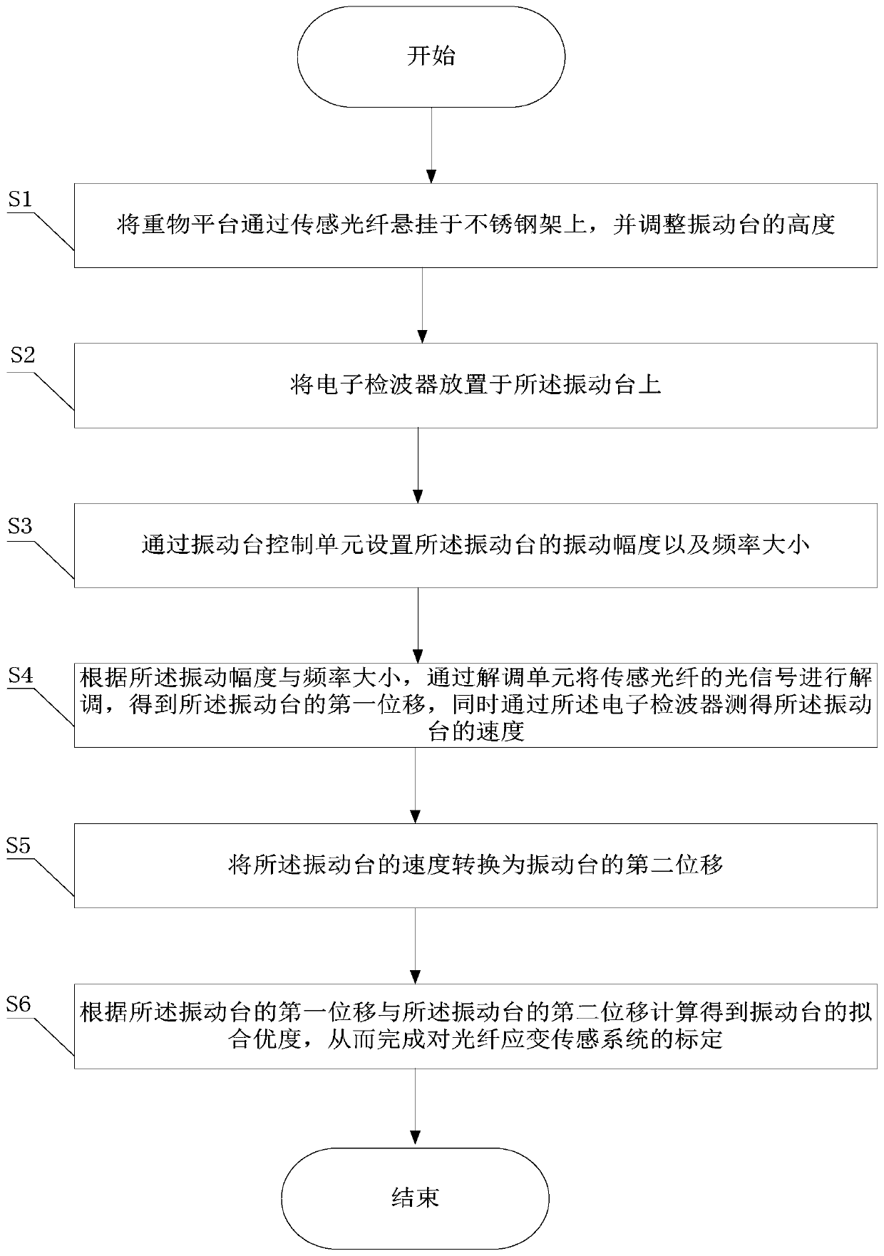
[0058] Such as figure 1 As shown, a calibration method of an optical fiber strain sensing system is implemented as follows:

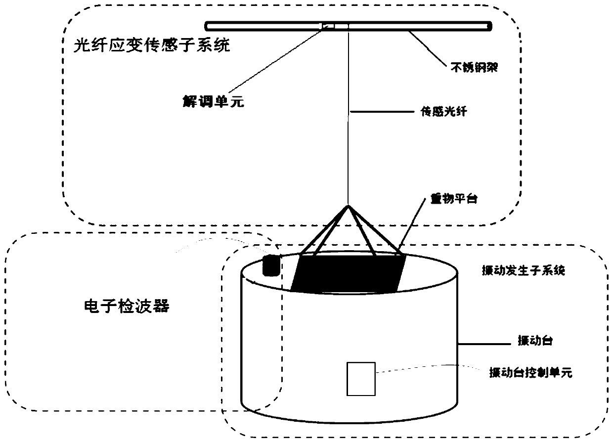
[0059] S1. Hang the heavy platform on the stainless steel frame through the sensing fiber, and adjust the height of the vibrating table, wherein the height of the stainless steel frame is at least 2 meters, and it is fixed on the ground, the length of the sensing fiber It is at least 20 meters long, and it is wound at least 10 times between the heavy platform and the stainless steel frame. The weight of the heavy platform is greater than 4kg. When the heavy platform is lifted by the sensing optical fiber, the weight The bottom surface of the object platform is kept level with the vibration table, and the sensing optical fiber is kept tight;

[0060] S2. Place an electronic detector on the vibrating table, where the electronic detector is a PS-10R velocity electronic detector;

[0061] S3. Set the vibration amplitude and frequency of the vibration table throu...


PUM


Abstract

The invention provides a method for calibrating an optical fiber strain sensing system: suspend a heavy object platform on a stainless steel frame through a sensing optical fiber, and adjust the height of the vibrating table; place an electronic wave detector on the vibrating table; Vibration amplitude and frequency; according to the vibration amplitude and frequency, the first displacement of the vibrating table is obtained, and the speed of the vibrating table is measured by the electronic detector; the speed of the vibrating table is converted into the second displacement of the vibrating table; the vibration table is calculated The goodness of fit, thus completing the calibration of the optical fiber strain sensing system. The invention also provides a calibration device for the optical fiber strain sensing system. The invention enables the sensing optical fiber and the electronic wave detector to simultaneously measure the motion process of the vibrating table, and fits the motion information measured separately, and the deformation of the sensing optical fiber can be matched with the vibration amplitude of the vibrating table, thereby improving the performance of the optical fiber. The accuracy of the strain sensing system ensures the rationality and feasibility of the calibration method.

Description

Technical field [0001] The invention belongs to the technical field of optical fiber sensing, and particularly relates to a calibration method and device of an optical fiber strain sensing system. Background technique [0002] As the fiber optic strain sensing technology becomes more mature, and it has begun to replace electronic detectors in some applications, but whether the strain measured by the fiber optic sensing system is consistent with the actual strain, the vibration frequency range and vibration amplitude range that can be accurately measured How much is it? These questions need to be rigorously calibrated to determine the answer. At present, there is no effective calibration scheme, which can not only make the strain of the optical fiber accurately reflect the movement of the vibration table, but also make the electronic geophone correspond to the physical quantity measured by the optical fiber strain sensing system. Summary of the invention [0003] In view of the ab...

Claims


Application Information

Patent Timeline
Patent Type & Authority Patents(China)
IPC IPC(8): G01H9/00G01H11/06
CPCG01H9/006G01H11/06
Inventor 冉曾令程建凯饶云江
Owner UNIV OF ELECTRONICS SCI & TECH OF CHINA
Learn More