Wind field test device for planar membrane window

A test device and flat membrane technology, applied in the direction of measuring device, aerodynamic test, machine/structural component test, etc., can solve the problems of difficult transportation, low test site requirements, high test cost, etc.

Active Publication Date: 2019-08-23
ZHENGZHOU UNIV +1
View PDF5 Cites 2 Cited by
  • Summary
  • Abstract
  • Description
  • Claims
  • Application Information

AI Technical Summary

Problems solved by technology

[0002] Usually the wind field test of plane membrane material window can be carried out under wind tunnel usually, but the test cost of this type of test is very high, and transportation is difficult; Based on the above reasons, the wind field test of a kind of plane membr

Method used


Image

  • Wind field test device for planar membrane window
  • Wind field test device for planar membrane window
  • Wind field test device for planar membrane window

Examples


Embodiment 1

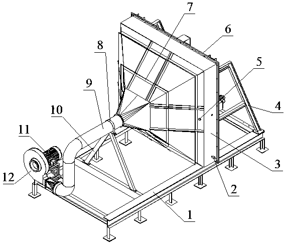
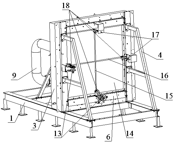
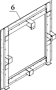
[0018] Such as Figure 1-6 Shown, a kind of wind field test device of plane membrane material window, it comprises base 1, and the upper surface of described base 1 is provided with test frame assembly 6, and wind shield 3 is fixed on the described test frame assembly 6, so The left end of the air cover 3 is connected to the fan 12 through the air duct 9, the fan 12 is connected to the motor 11, and the right end of the air cover 3 is sealed and fixedly connected with a plane film material window 14, and the plane film material The outer side of the window 14 is provided with a cross rope A15 and a rope B16, and one end of the rope A15 and the rope B16 respectively bypasses the pulley assembly 18 and is connected to the tension sensor 17, and the other end of the tension sensor 17 is fixed On the test frame assembly 6, the other ends of the rope A15 and the rope B16 go around the pulley assembly 18 and are connected to the rope fixing shaft 23 of the tensioner assembly 13, bet...

Embodiment 2

[0021] Such as Figure 1-6 Shown, a kind of wind field test device of plane membrane material window, it comprises base 1, and the upper surface of described base 1 is provided with test frame assembly 6, and wind shield 3 is fixed on the described test frame assembly 6, so The left end of the air cover 3 is connected to the fan 12 through the air duct 9, the fan 12 is connected to the motor 11, and the right end of the air cover 3 is sealed and fixedly connected with a plane film material window 14, and the plane film material The outer side of the window 14 is provided with a cross rope A15 and a rope B16, and one end of the rope A15 and the rope B16 respectively bypasses the pulley assembly 18 and is connected to the tension sensor 17, and the other end of the tension sensor 17 is fixed On the test frame assembly 6, the other ends of the rope A15 and the rope B16 go around the pulley assembly 18 and are connected to the rope fixing shaft 23 of the tensioner assembly 13, bet...


PUM


Abstract

The invention relates to a wind field test device for a planar membrane window. The wind field test device comprises a base, wherein an upper surface of the base is provided with a test frame assembly; an air shield is fixed on the test frame assembly; a left end of the air shield is connected with a fan through an air pipe; the fan is connected with a motor; a right end of the air shield is hermetically and fixedly connected with a planar membrane window; an outer side of the planar membrane window is provided with a rope A and a rope B which are intersected; one end of the rope A and one endof the rope B are connected to a tension sensor after passing through a pulley assembly, the other end of the tension sensor is fixed on the test frame assembly; the other ends of the rope A and therope B are connected to a rope fixing shaft of a tension device assembly after passing through the pulley assembly; a support shaft is connected between the test frame assembly and the base; a side face of the air shield is provided with an air outlet and an air pressure sensor interface; and the air pressure sensor interface is connected with an air pressure sensor. The wind field test device hasthe advantages of simple structure, convenience in use, low test cost, and low test field requirement.

Description

technical field [0001] The invention relates to a wind field test device, in particular to a wind field test device for a plane film window. Background technique [0002] Usually the wind field test of plane membrane material window can be carried out under wind tunnel usually, but the test cost of this type of test is very high, and transportation is difficult; Based on the above reasons, the wind field test of a kind of plane membrane material window of the present invention The device can not only solve the above problems, but also ensure the accurate determination of the wind field test of the flat membrane window, reduce the test cost, and at the same time have low requirements for the test site. Contents of the invention [0003] The purpose of the present invention is to overcome the deficiencies in the prior art, and provide a wind field test device for flat membrane windows with simple structure, convenient use, low test cost and low test site requirements. [00...

Claims


Application Information

Patent Timeline
IPC IPC(8): G01M9/04G01M9/02
CPCG01M9/02G01M9/04
Inventor 牛鹏辉周洋李延民李大磊
Owner ZHENGZHOU UNIV
Why Eureka
Try Eureka