
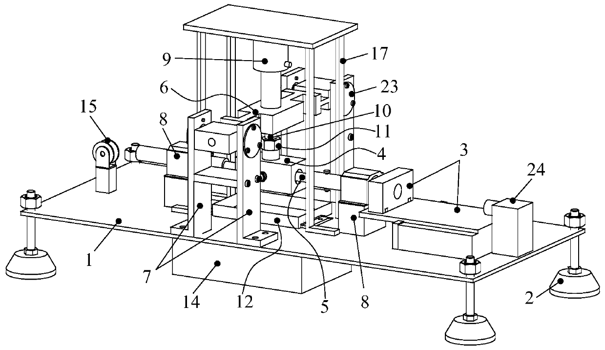
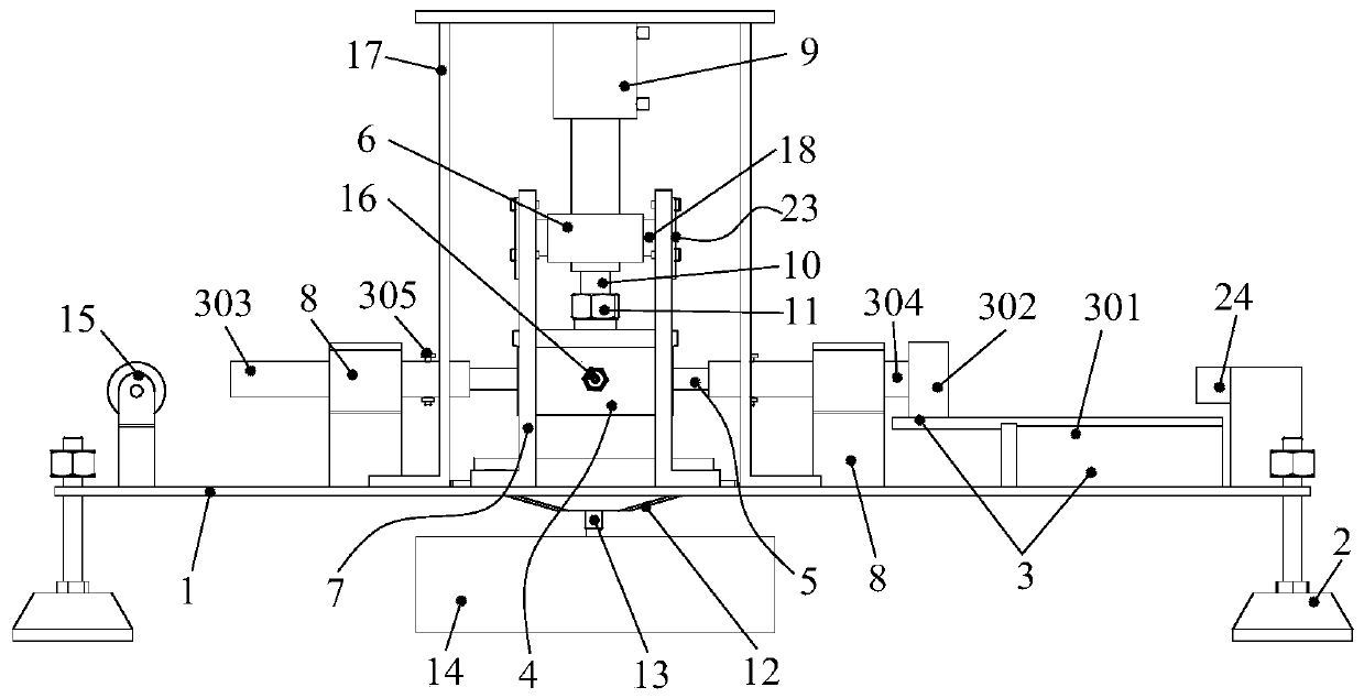
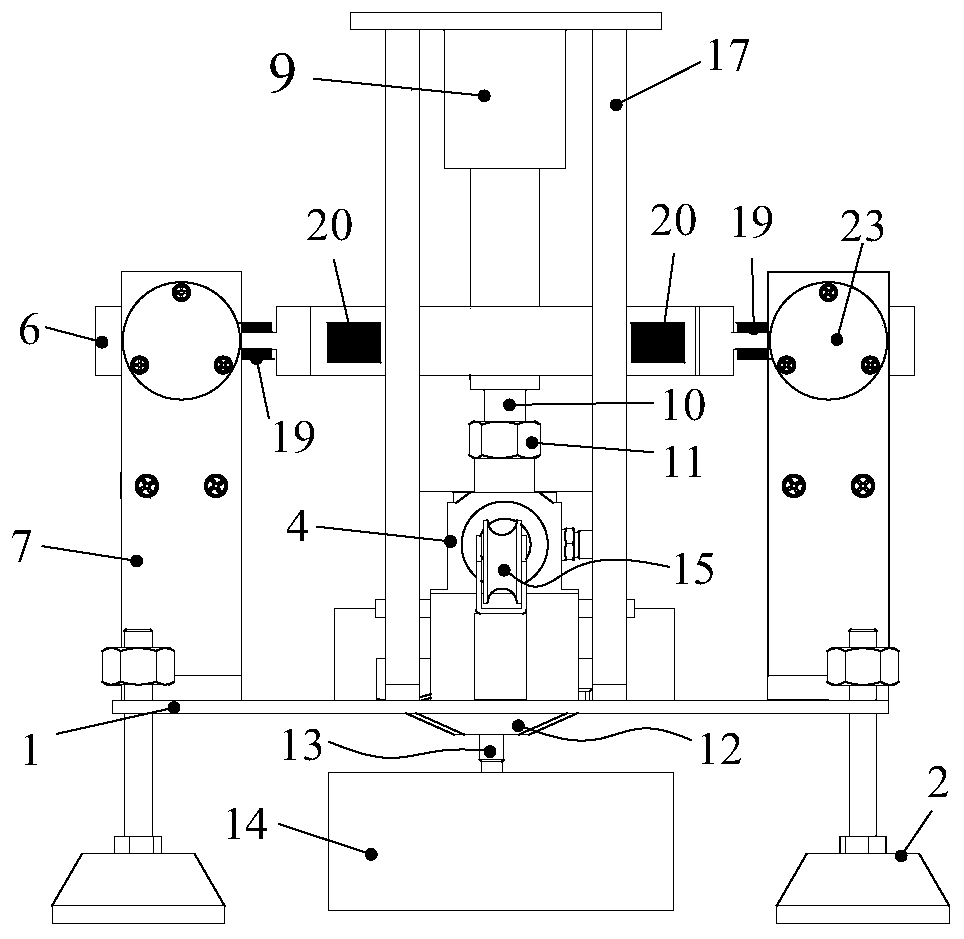
Working condition variable reciprocating friction and wear tester based on double-degree-of-freedom flexible hinge

A friction and wear test, flexible hinge technology, applied in the direction of strength characteristics, testing wear resistance, measuring devices, etc., can solve the problem of difficult to achieve fast response to variable load, variable speed, variable friction pair end face pressure, etc., to improve stability stability and measurement accuracy, avoid mutual interference, and avoid the effects of poor stability

Pending Publication Date: 2019-08-23
ANHUI UNIV OF SCI & TECH
View PDF0 Cites 7 Cited by
  • Summary
  • Abstract
  • Description
  • Claims
  • Application Information

AI Technical Summary

Problems solved by technology

[0010] The technical problem to be solved by the present invention is to provide a variable working condition reciprocating friction and wear testing machine based on a two-degree-of-freedom flexible hinge, which solves the problem that the traditional reciprocating friction and wear testing machine is diffic

Method used


Image

  • Working condition variable reciprocating friction and wear tester based on double-degree-of-freedom flexible hinge
  • Working condition variable reciprocating friction and wear tester based on double-degree-of-freedom flexible hinge
  • Working condition variable reciprocating friction and wear tester based on double-degree-of-freedom flexible hinge

Examples


Embodiment Construction

[0038] In order to make the technical means, creative features, objectives and effects achieved by the present invention easy to understand, the present invention will be further described below in conjunction with specific embodiments and illustrations. However, what has been described is only a part of the embodiments of the present invention, not all the embodiments. Based on the embodiments of the present invention, all other embodiments obtained by persons of ordinary skill in the art without creative work all belong to the protection scope of the present invention. In addition, the following "left, right, up, down, front, Orientation words such as "back" are only directions established based on the convenience of illustrations and descriptions, and others should not use them to raise rebuttals.

[0039] Such as figure 1 , figure 2 , image 3 and Figure 4 As shown, a reciprocating friction and wear testing machine based on a two-degree-of-freedom flexible hinge, inc...


PUM


Abstract

The invention discloses a working condition variable reciprocating friction and wear tester based on a double-degree-of-freedom flexible hinge. The tester comprises a worktable, a holder, a supportingframe, an upper test piece, a lower test piece, the double-degree-of-freedom flexible hinge, a loading cylinder, strain gauges I, strain gauges II, a force sensor, a hydraulic loading and control system, a controller and a reciprocating motion assembly. The upper test piece is driven by the reciprocating motion assembly. Positive pressure is applied through utilization of the loading cylinder. Friction is generated between the test pieces. The double-degree-of-freedom flexible hinge is forced to deform through utilization of the friction. Deformation is transformed into electric signals through utilization of the strain gauges I and the strain gauges II. Further the controller computes magnitude of friction force. Magnitude of the positive pressure and liquid pressure difference between two ends of a friction pair between the test pieces are sensed and controlled in real time through utilization of the hydraulic loading and control system, the controller and the force sensor. According to the tester, friction load, friction pair end face liquid pressure difference and friction speed can be dynamically adjusted, friction force under variable working condition can be measured dynamically in real time, and stability is relatively high.

Description

technical field [0001] The invention relates to a friction testing machine, in particular to a reciprocating friction and wear testing machine based on a double-degree-of-freedom flexible hinge. Background technique [0002] The reciprocating friction and wear testing machine is a kind of testing equipment that can be used to test the tribological performance of metal or non-metallic material moving pairs. In the field of tribology, the development of friction testing machine and the theoretical research of tribology are regarded as equally important. Therefore, the development of high Performance friction and wear testing machine is of great significance. [0003] At present, most common friction and wear testing machines are rotating friction and wear testing machines, and there are few reciprocating friction and wear testing machines, and the existing reciprocating friction and wear testing machines mainly have the following problems: [0004] First of all, the friction ...

Claims


Application Information

Patent Timeline
IPC IPC(8): G01N3/56G01N3/02
CPCG01N3/02G01N3/56G01N2203/0005G01N2203/0048G01N2203/005G01N2203/0676G01N2203/0682
Inventor 何涛李金苗李成陈国瑜朱路生张宇张文标骆元庆
Owner ANHUI UNIV OF SCI & TECH
Learn More