Joint Estimation Method of Signal Frequency and 2D DoA Based on Double L-shaped Array

A technology of signal frequency and joint estimation, applied in the field of signal processing, can solve the problem of high sampling rate of multi-band signals

Active Publication Date: 2020-11-13
HARBIN INST OF TECH
View PDF6 Cites 0 Cited by
  • Summary
  • Abstract
  • Description
  • Claims
  • Application Information

AI Technical Summary

Problems solved by technology

[0006] The purpose of the present invention is to solve the problem of high sampling rate required for realizing the joint estimation of two-dimensional DOA and carrier frequency of multi-band signals and the accurate reconstruction of multi-band signals under the traditional sampling theory, and proposes a method based on dual Joint estimation method of signal frequency and two-dimensional DOA of L-shaped array

Method used


Image

  • Joint Estimation Method of Signal Frequency and 2D DoA Based on Double L-shaped Array
  • Joint Estimation Method of Signal Frequency and 2D DoA Based on Double L-shaped Array
  • Joint Estimation Method of Signal Frequency and 2D DoA Based on Double L-shaped Array

Examples


specific Embodiment approach 1

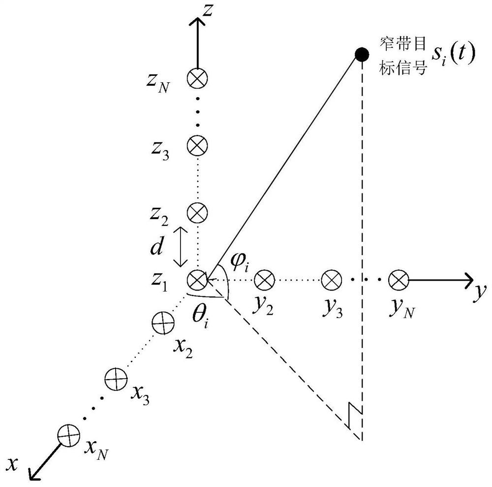
[0045] Specific implementation mode one: as figure 1 shown. The method for jointly estimating signal frequency and two-dimensional DOA based on double L-shaped arrays described in this embodiment includes the following steps:

[0046] Step 1. Establish a double L-shaped array composed of sensors uniformly distributed in the positive direction of the x-axis, the positive direction of the y-axis, and the positive direction of the z-axis of the three-dimensional space rectangular coordinate system. Each sensor is connected to a MWC (modulation bandwidth converter) channel , the signal received by the sensor and the period is T p After the pseudo-random sequence p(t) is mixed, the mixed signal is obtained, and the mixed signal passes through the cut-off frequency f s / 2 low-pass filter with f s The frequency is sampled to obtain the sampled value;

[0047] There are N sensors uniformly distributed in the positive direction of the x-axis {x 1 ,x 2 ,...,x N}, there are N sens...

specific Embodiment approach 2

[0075] Specific implementation mode two: the difference between this implementation mode and specific implementation mode one is: the specific process of the step one is:

[0076]

[0077] Among them: x[k], y[k] and z[k] are the sensor sampling values ​​on the x-axis, y-axis and z-axis respectively, A x 、A y and A z are the array flow pattern matrix of the x-axis, y-axis and z-axis respectively, and the elements in the array flow pattern matrix are only related to the unknown carrier frequency, azimuth angle and elevation angle; w[k] is the signal after the narrowband target signal is moved to the baseband, w[k]={w 1 [k],w 2 [k],...,w M [k]}, w 1 [k],w 2 [k],...,w M [k] respectively represent the narrowband target signal s 1 (t),s 2 (t),...,s M (t) The form after moving to the baseband.

specific Embodiment approach 3

[0078] Specific implementation mode three: the difference between this implementation mode and specific implementation mode two is: the specific process of said step two is:

[0079]

[0080] where: x 1 [k] represents the sensor sampling value of the first sub-array of the x-axis, x 2 [k] represents the sensor sampling value of the second sub-array of the x-axis, and Respectively represent the array flow matrix of the first sub-array and the second sub-array of the x-axis;

[0081] the y 1 [k] represents the sensor sampling value of the first sub-array of the y-axis, y 2 [k] represents the sensor sampling value of the second sub-array of the y-axis, and Represent the array flow matrix of the first sub-array and the second sub-array of the y-axis;

[0082] z 1 [k] represents the sensor sampling value of the first sub-array of the z-axis, z 2 [k] represents the sensor sampling value of the second sub-array of the z-axis, and Represents the array flow matrix o...


PUM


Abstract

The invention relates to a signal frequency and two-dimensional DOA joint estimation method based on a double-L-type array, and belongs to the technical field of signal processing. The method solves the problem that high sampling rate is required by realization of multi-frequency-band signal two-dimensional DOA and carrier frequency joint estimation, and accurate reconstruction of the multi-frequency-band signal under the traditional sampling theory. A double-L-type array sensor is used for acquiring signals; an under-sampling value of a three-axis array is obtained through a modulated wideband converter system; under a condition that three-dimensional parameter pairing is not needed, the two-dimensional DOA and the carrier frequency parameters of the signal can be obtained; finally, the time domain waveform of the signal is recovered; and the multi-frequency-band signal two-dimensional DOA and carrier frequency joint estimation, and accurate reconstruction of the multi-frequency-bandsignal can be realized at a relatively low sampling rate, so that the problem that a traditional method needs high sampling rate is solved. The method can be applied to the technical field of signal processing.

Description

technical field [0001] The invention belongs to the technical field of signal processing, and in particular relates to a joint estimation method of signal frequency and two-dimensional DOA. Background technique [0002] Multi-band signal is a common signal form in the fields of ultra-wideband communication, radar detection, cognitive radio, and spectrum monitoring. It is an important application problem to detect the information carried by multi-band signal in the airspace and frequency domain. In the practical application environment, it is often necessary to estimate multiple parameters of the array at the same time, and the joint estimation of the frequency of the array signal and the two-dimensional direction-of-arrival (DOA) is an important direction for the multi-parameter estimation of the array signal in the space-frequency domain. [0003] However, with the rapid development of information and communication technology, the bandwidth of the signal carrying informatio...

Claims


Application Information

Patent Timeline
Patent Type & Authority Patents(China)
IPC IPC(8): G01S3/16G01S3/28G01R23/02G01S7/02G01S13/28
CPCG01R23/02G01S3/16G01S3/28G01S7/02G01S13/28
Inventor 付宁姜思仪尉志良乔立岩
Owner HARBIN INST OF TECH
Why Eureka
Try Eureka