Method for operating a brake system, and brake system

A brake system and brake circuit technology, which is applied in the direction of brake control system, brake transmission device, brake action start device, etc., can solve the problems of not performing area conversion, etc., and achieve the elimination of adverse effects, accurate system pressure, The effect of fine tuning

Active Publication Date: 2019-08-23
CONTINENTAL AUTOMOTIVE TECH GMBH
View PDF7 Cites 3 Cited by
  • Summary
  • Abstract
  • Description
  • Claims
  • Application Information

AI Technical Summary

Problems solved by technology

[0003] The disadvantage of this approach is that this area conversion is not done on the forward pass

Method used


Image

  • Method for operating a brake system, and brake system

Examples


Embodiment Construction

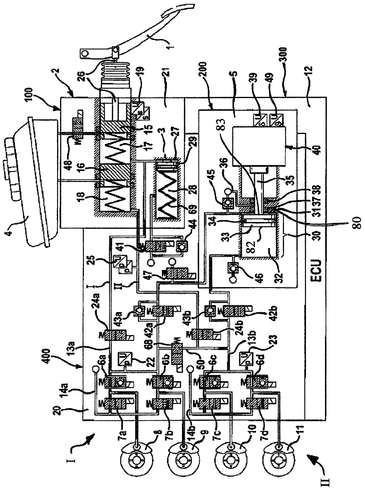
[0036] The brake system shown comprises a hydraulic pedal decoupling unit 2 which can be actuated by means of an actuation or brake pedal 1, a pedal feel simulator 3 which interacts with the hydraulic pedal decoupling unit 2, a A pressure medium storage container 4, an electrically controllable pressure supply device 5, an electrically controllable pressure modulation device 20, and an electronic control and regulation unit 12, said pressure modulation device comprising inlet valves 6a-6d and outlet valves 7a-7d and in The wheel brakes 8 , 9 , 10 , 11 (not shown) of the motor vehicle are connected to their outlet connections, and the electronic control and regulation unit is used to process sensor signals and to actuate electrically controllable components.

[0037] In the "brake-by-wire" operating mode, the inlet connections of the inlet valves 6a-6d are supplied with a pressure called system pressure by means of system pressure lines 13a, 13b, wherein pressure sensors 22, 23 ...


PUM


Abstract

The invention relates to a method for operating a brake system for motor vehicles having hydraulic wheel brakes (8, 9, 10, 11); a pressure medium storage tank (4) under atmospheric pressure; a pressure modulation unit (20) for setting brake pressures for individual wheels, an electrohydraulic pressure generating device (5) which is connected to the pressure modulation unit (20) and to the pressuremedium storage tank (4) and which transmits the brake system pressure to the pressure modulation unit (20) and draws in pressure medium from the pressure medium storage tank (4) to adjust the volumebalance of said unit; a first (42a) and a second pressure sequence valve (42b) for connecting the pressure generating device (5) to the pressure modulation device (5). The pressure generating device (5) comprises a double-acting piston / cylinder arrangement (30), wherein a piston (33) of the piston / cylinder arrangement (30) separates two pressure chambers (31, 32) from one another, wherein a pressure build-up takes place in the first pressure chamber (31) during a backward movement of the piston (33) and in the second pressure chamber (32) during a forward movement of the piston (33). During abuild-up of brake pressure, by a forward stroke of the piston (33) of the piston / cylinder arrangement (30) in a predetermined situation the sequence valve (42a) is opened and the first pressure chamber (31) is separated hydraulically from the pressure medium storage tank (4), the two pressure chambers (31, 32) being hydraulically connected to one another.

Description

technical field [0001] The invention relates to a method for operating a brake system of a motor vehicle, which in a brake-by-wire operating mode can be actuated not only by the vehicle driver but independently of the vehicle driver, preferably in the brake-by-wire operating mode In operation, the brake system has: hydraulic wheel brakes, wherein two wheel brakes are hydraulically assigned to the first brake circuit and two wheel brakes are hydraulically assigned to the second brake circuit; a pressure medium reserve at atmospheric pressure Container; electronic control and regulating unit; pressure modulation unit for regulating the wheel-specific brake pressure derived from the brake system pressure; electrohydraulic pressure supply connected to the pressure modulation unit and the pressure medium storage tank, which delivers the brake system pressure to the pressure modulation unit, from which pressure medium is re-absorbed from the pressure medium storage tank in order to ...

Claims


Application Information

Patent Timeline
Patent Type & Authority Applications(China)
IPC IPC(8): B60T13/74
CPCB60T7/042B60T13/146B60T13/662B60T13/686B60T13/745B60Y2400/81B60T13/741B60T2270/602F16D65/18
Inventor M·贝西尔S·德鲁姆J·博姆
Owner CONTINENTAL AUTOMOTIVE TECH GMBH
Why Eureka
Try Eureka