A test device, system and method for simulating long-term axial load and impact coupling disasters of components
A test method and axial load technology, applied in the testing of machine/structural components, impact testing, measuring devices, etc., can solve the problems such as test loading devices that have not been seen yet, and achieve fast construction speed, convenient disassembly, and reasonable stress. reliable results
- Summary
- Abstract
- Description
- Claims
- Application Information
AI Technical Summary
Problems solved by technology
Method used
Image
Examples
specific Embodiment approach 1
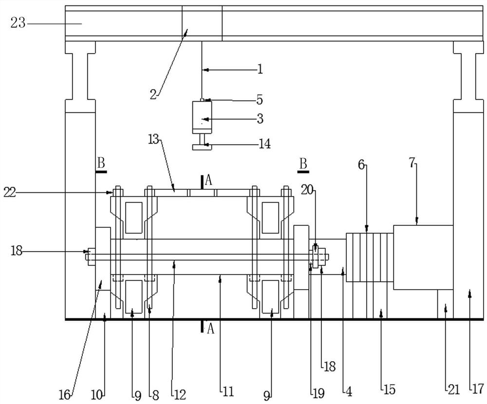
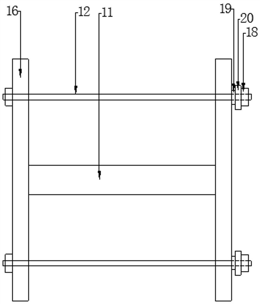
[0029] Specific implementation plan one: the following combination image 3 , 4 , 5 specifically describe this embodiment. What this embodiment describes is a long-term axial load loading device for simulating components. 11, and two thin gaskets 20. It is characterized in that each rigid plate 16 has two symmetrical reserved bolt holes, and the middle of each thin gasket also has reserved bolt holes, and the sensor is specially made, and each sensor also has a reserved hole in the middle. Place the component on the loading platform (test piece support), place a rigid plate 16 at both ends of the component 11, place a pressure sensor 19 at one end of the rigid plate, and set a shallow circular groove in the middle of the outermost edge of the rigid plate on the side with the pressure sensor. There is also a thin spacer 20 and a reinforcing nut 18, and another reinforcing nut made of steel at the other end of another rigid plate. Use the pull bolt rod 12 to pass through the...
specific Embodiment approach 2
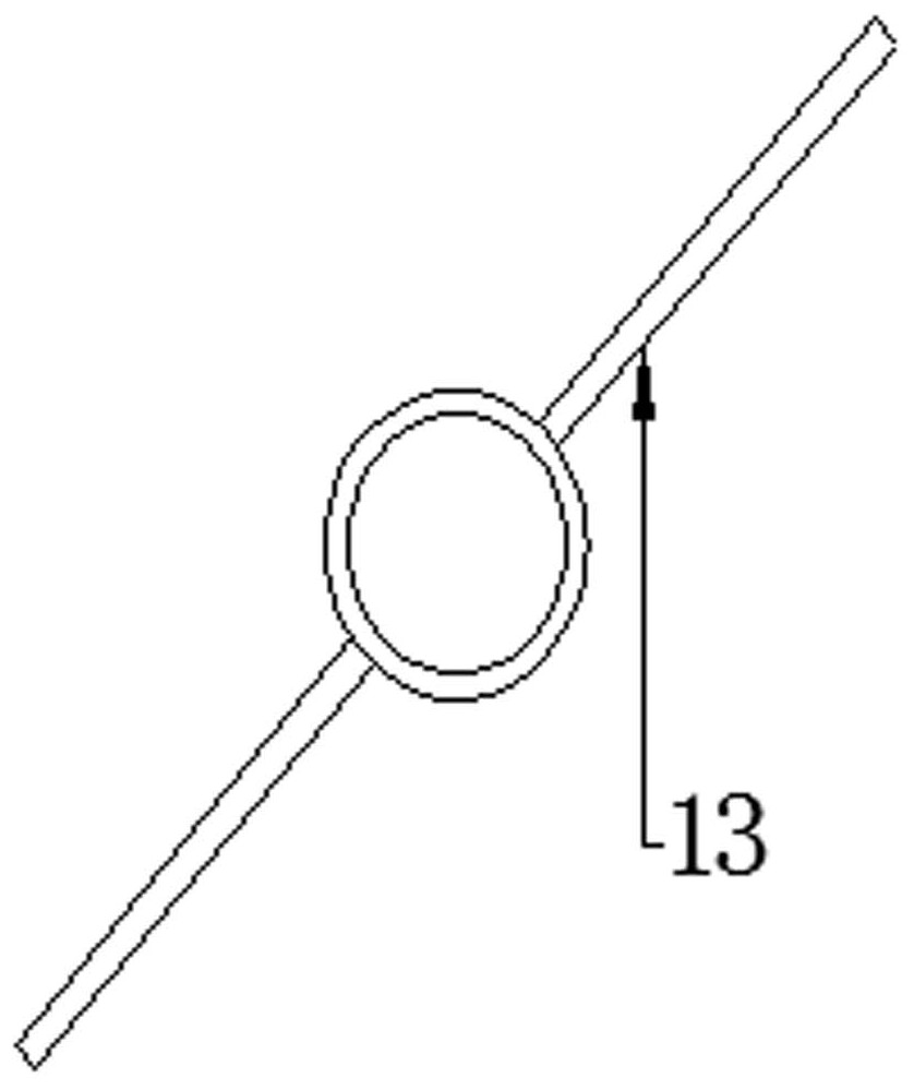
[0030] Specific implementation scheme two: combine below Figure 2~6This embodiment will be specifically described. Described in this embodiment is a test device for simulating components subjected to long-term loads and shock coupling disaster tests. Specimen supports 9, wherein the upper and lower two supports are fixed by ground bolts 8. Rigid plate supports 10 are provided at both ends of the specimen support 9 to fix the rigid plate 16 and the rigid plate supports 10 . There is a falling weight protection frame 13 above the bearing, and the falling weight protection frame is fixed on the ground bolt rod 8 of the diagonal. Immediately above the falling weight protective frame 13 are impact force sensors and falling weights 3 . The sensor of the hammer head is externally connected to the computer, and the drop hammer is fixed on the uncoupling device 5, and the uncoupling device 5 and the electric hoist crane 2 are connected by a telescopic sling 1. There is a shallow c...
PUM
 Abstract
Description
Claims
Application Information
 - R&D
- Intellectual Property
- Life Sciences
- Materials
- Tech Scout
- Unparalleled Data Quality
- Higher Quality Content
- 60% Fewer Hallucinations
Browse by: Latest US Patents, China's latest patents, Technical Efficacy Thesaurus, Application Domain, Technology Topic, Popular Technical Reports.
© 2025 PatSnap. All rights reserved.Legal|Privacy policy|Modern Slavery Act Transparency Statement|Sitemap|About US| Contact US: help@patsnap.com


