
Display device, liquid crystal display panel and driving method of liquid crystal display panel

A liquid crystal display panel and liquid crystal layer technology, which is applied in optics, instruments, character and pattern recognition, etc., can solve the problems that fingerprint recognition technology is difficult to apply to liquid crystal display panels and difficult to display images, etc.

Active Publication Date: 2019-08-27
BOE TECH GRP CO LTD
View PDF8 Cites 10 Cited by
  • Summary
  • Abstract
  • Description
  • Claims
  • Application Information

AI Technical Summary

Problems solved by technology

However, for liquid crystal display panels, if a light-shielding layer with small holes is provided in the liquid crystal display panel, the light-shielding layer will block the light of the backlight module, making it difficult to display images, which makes it difficult to apply fingerprint recognition technology to liquid crystal display panels. display panel

Method used


Image

  • Display device, liquid crystal display panel and driving method of liquid crystal display panel
  • Display device, liquid crystal display panel and driving method of liquid crystal display panel
  • Display device, liquid crystal display panel and driving method of liquid crystal display panel

Examples


Embodiment Construction

[0052] Example embodiments will now be described more fully with reference to the accompanying drawings. Example embodiments may, however, be embodied in many forms and should not be construed as limited to the embodiments set forth herein; rather, these embodiments are provided so that this disclosure will be thorough and complete, and will fully convey the concept of example embodiments to those skilled in the art. The same reference numerals in the drawings denote the same or similar structures, and thus their detailed descriptions will be omitted. Furthermore, the drawings are merely schematic illustrations of the present disclosure and are not necessarily drawn to scale.

[0053] Although relative terms such as "upper" and "lower" are used in this specification to describe the relative relationship of one component of an icon to another component, these terms are used in this specification only for convenience, for example, according to the description in the accompanyin...


PUM


Abstract

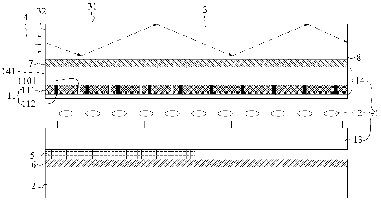
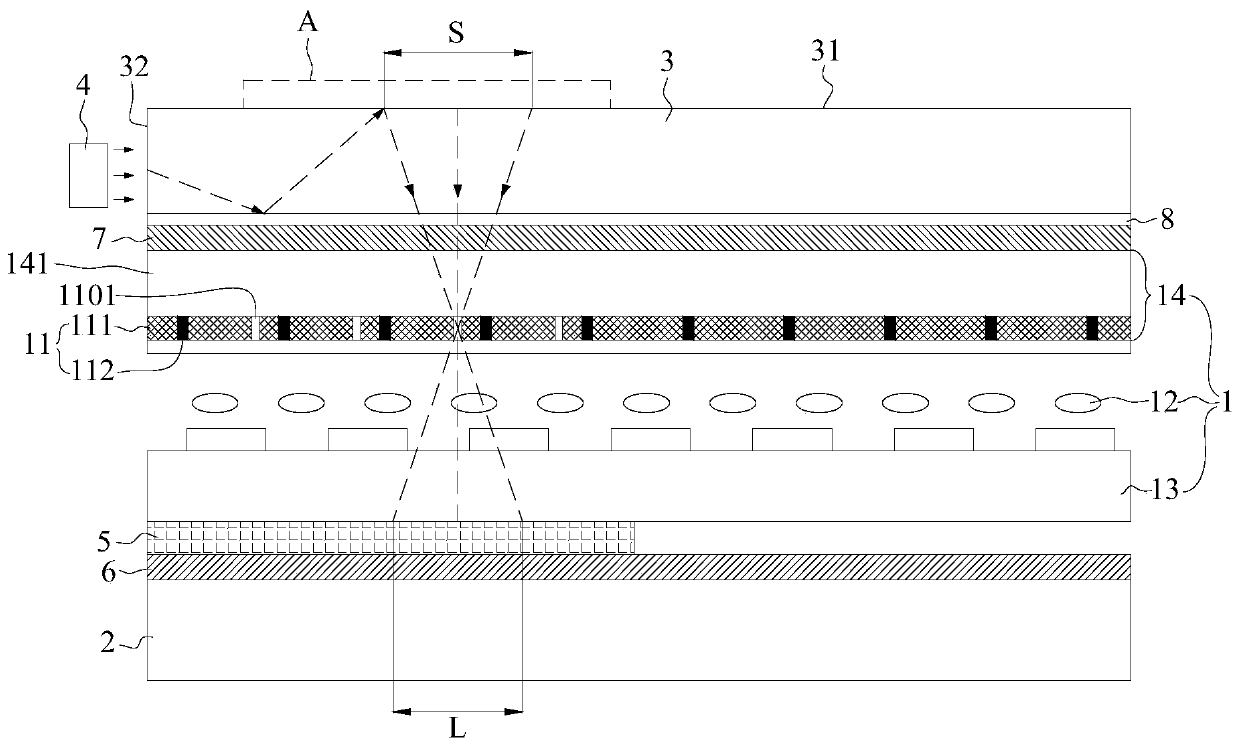
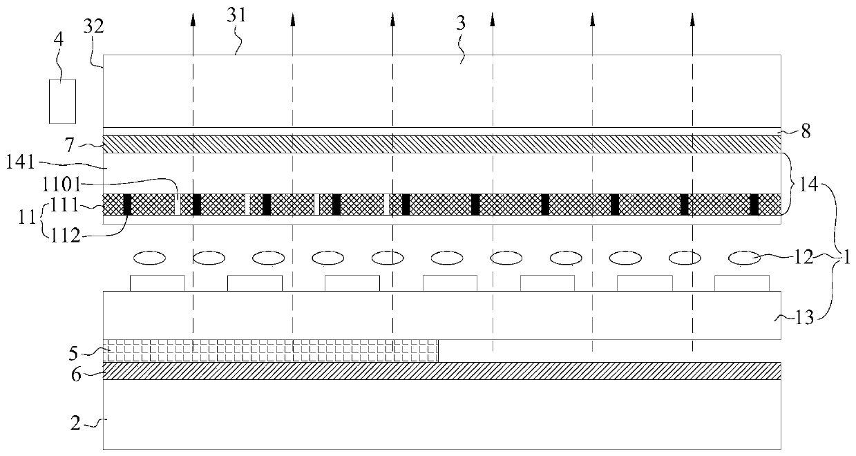
The invention provides a display device, a liquid crystal display panel and a driving method of the liquid crystal display panel, and relates to the technical field of display. The liquid crystal display panel comprises a display module, a backlight module, a light guide layer, an identification light source and an identification light sensing circuit. The display module comprises a liquid crystallayer and a color film layer located on one side of the liquid crystal layer, wherein the color film layer comprises a plurality of light filtering areas, and the light filtering area is provided with a plurality of light transmitting holes used for allowing identification light rays to transmit; the backlight module is arranged on the backlight side of the display module; the light guide layer has a contact surface and a back surface which are opposite to each other, and the back surface faces the display module; the identification light source is used for emitting the identification light rays in the light guide layer, and the identification light rays are invisible light or visible light which is different from the color of each light filtering area, and at least part of the identification light rays entering the light guide layer can generate total reflection between the back surface and the contact surface; and the identification light sensing circuit is arranged on one side, opposite to the light guide layer, of the color film layer and is used for sensing the identification light rays of the identification light source and generating a fingerprint signal.

Description

technical field [0001] The present disclosure relates to the field of display technology, and in particular, to a display device, a liquid crystal display panel, and a driving method for the liquid crystal display panel. Background technique [0002] At present, the technology of realizing fingerprint recognition on the display panel has been widely used. Among them, the display panel with fingerprint recognition function is usually an OLED (Organic Light-Emitting Diode, organic light-emitting diode) display panel, and the light emitted by the organic light-emitting layer passes through the After the fingerprint is reflected, it passes through the small hole on the light-shielding layer on the side of the organic light-emitting layer away from the finger to reach the fingerprint identification device, so as to obtain fingerprint information. However, for liquid crystal display panels, if a light-shielding layer with small holes is provided in the liquid crystal display panel...

Claims


Application Information

Patent Timeline
IPC IPC(8): G02F1/1333G02F1/13357G06K9/00
CPCG02F1/13338G02F1/133615G06V40/1318
Inventor 张永忠苏京程晓萍
Owner BOE TECH GRP CO LTD
Learn More