Speed reducer fixing device for roll gang

A conveyor roller table and fixing device technology, applied in the field of conveyor roller table reducer fixing devices, can solve the problems of fatigue fracture of connecting bolts and connecting plates, difficult maintenance, and time-consuming, etc., to solve vibration problems and stress problems, reduce the danger of workers, and eliminate the effect of fatigue fracture

Active Publication Date: 2019-08-30
MAANSHAN IRON & STEEL CO LTD
View PDF4 Cites 2 Cited by
  • Summary
  • Abstract
  • Description
  • Claims
  • Application Information

AI Technical Summary

Problems solved by technology

[0002] The slab produced by the existing continuous casting needs to be transported through the conveying roller table. The power source of the transportation is that the reducer drives the conveying roller to rotate, that is, the reducer is fixed on the reducer fixing device, and the motor drives the reducer to rotate, and then the conveying roller rotates. , the fixing device has the following defects during use: 1. The fixing device provides a fixed point for the reducer and the motor. If the fixed point cannot function normally, the reducer and the motor will rotate around the conveyor roller shaft after losing the fixed point. The power cannot be normally transmitted to the billet to make it move forward. This is a point of failure in production; 2. The fixing device is too simple, and the reducer is only connected by a connecting plate and a fixing bolt, and the connecting bolt and the connecting plate of the reducer Fatigue fractures often occur; 3. The fixing device is located under the reducer, the space is narrow, the maintenance is difficult and time-consuming, and the maintenance frequency is high; 4. Since the reducer and the motor have only one fixed point, and the fixed The point is not on the center of gravity of the reducer and the motor as a whole, resulting in poor overall stability of the reducer and the motor; 5. Since the location of the fixing device is not conducive to the maintenance of the maintenance workers, there are hidden dangers to the safety of personnel in regular maintenance
Therefore, the existing structure cannot meet the demand

Method used


Image

  • Speed reducer fixing device for roll gang
  • Speed reducer fixing device for roll gang
  • Speed reducer fixing device for roll gang

Examples


Embodiment Construction

[0025] Below with reference to the accompanying drawings, through the description of the embodiments, the specific embodiments of the present invention, such as the shape, structure, mutual position and connection relationship between the various parts, the role and working principle of the various parts, etc., will be further described. Detailed instructions:

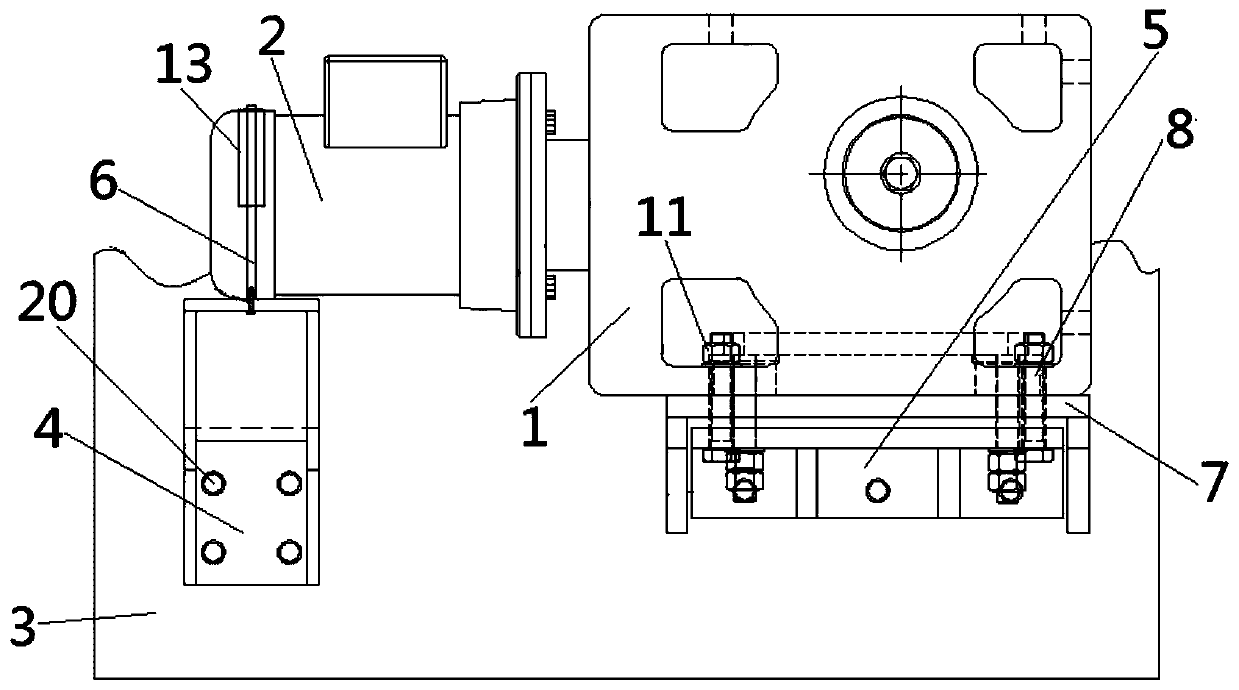
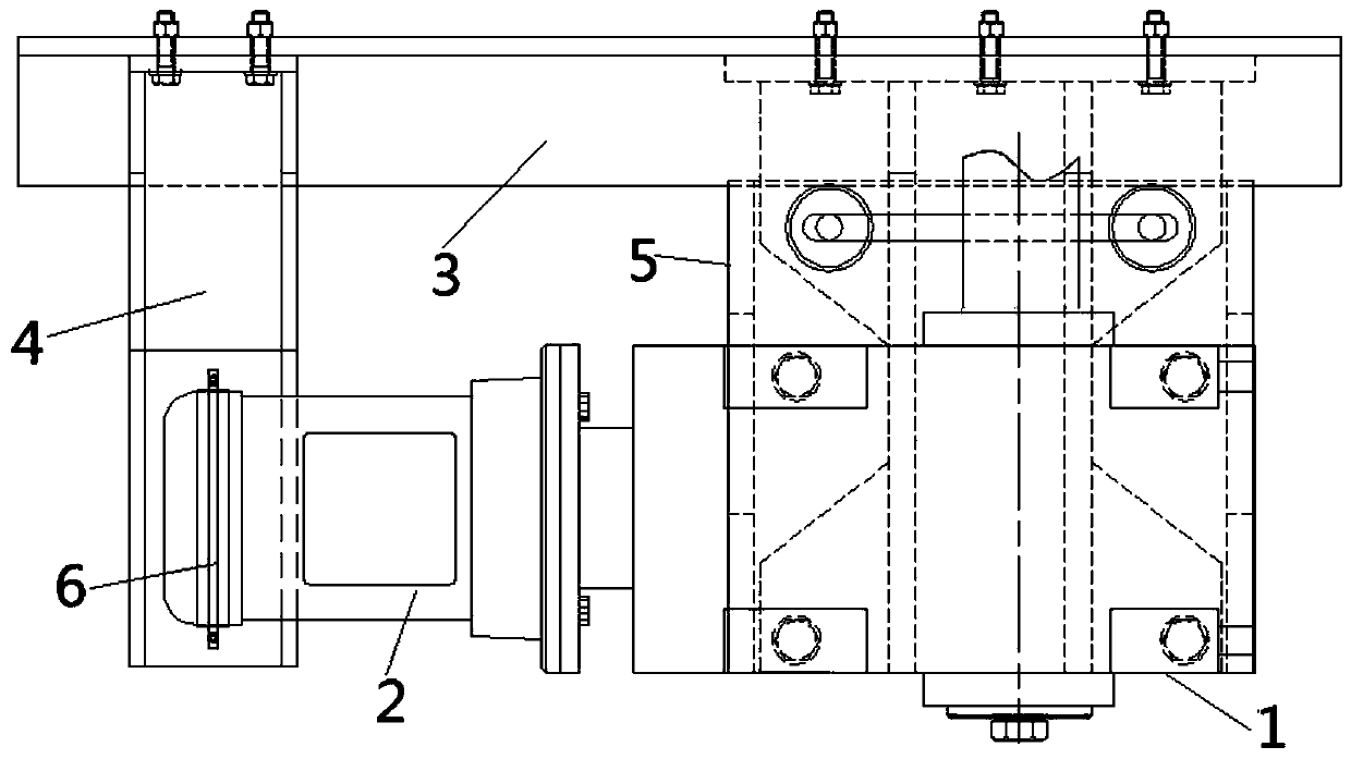
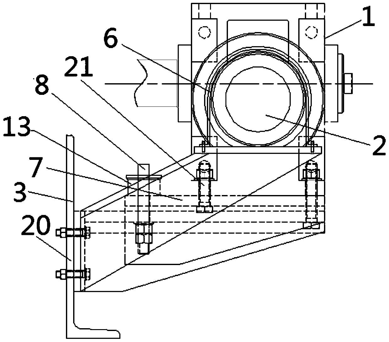
[0026] as attached figure 1 - attached Figure 7 As shown, the present invention is a conveyor roller reducer fixing device, the conveyor roller reducer includes a reducer body 1 and a reducer motor 2, the reducer body 1 and the reducer motor 2 are connected, and the conveying The roller table reducer fixing device includes a device support beam 3, a motor fixed chassis 4, and a reducer fixed chassis 5. The side of the motor fixed chassis 4 is connected to the support beam 1, and the reducer motor 2 is located above the motor fixed chassis 4. The motor The fixed belt 6 is set on the motor 2 of the reducer, and the fi...


PUM


Abstract

The invention provides a speed reducer fixing device for a roller gang, and belongs to the technical field of roller gang equipment of continuous machines. According to the speed reducer fixing devicefor the roller gang, the side face of a motor fixing chassis (4) is connected with a supporting beam (1), a motor fixing belt (6) is arranged on a speed reducer in a sleeving mode and is fixedly connected with a motor fixing disc (4), a speed reducer assembling base plate (7) is arranged at the lower end of a speed reducer body (2), the side face of a speed reducer fixing chassis (5) is connectedwith the supporting beam (1), and the speed reducer assembling base plate (7) is connected with the speed reducer fixing chassis (5). According to the speed reducer fixing device for the roller gang,fault points can be eliminated through the speed reducer body (horizontal speed reducer) fixing device, so that the overall stability of the speed reducer fixing device is improved, the dangers are reduced for workers, and the speed reducer fixing device has a positive effect on reducing the cost and improving the efficiency; and meanwhile, fixing device connecting bolts and connecting plates arenot needed, so that the strength is ensured, and fatigue fractures are prevented.

Description

technical field [0001] The invention belongs to the technical field of conveying roller table equipment for continuous casting machinery, and more specifically relates to a fixing device for a conveying roller table reducer. Background technique [0002] The slab produced by the existing continuous casting needs to be transported through the conveying roller table. The power source of the transportation is that the reducer drives the conveying roller to rotate, that is, the reducer is fixed on the reducer fixing device, and the motor drives the reducer to rotate, and then the conveying roller rotates. , the fixing device has the following defects during use: 1. The fixing device provides a fixed point for the reducer and the motor. If the fixed point cannot function normally, the reducer and the motor will rotate around the conveyor roller shaft after losing the fixed point. The power cannot be normally transmitted to the billet to make it move forward. This is a point of fa...

Claims


Application Information

Patent Timeline
Patent Type & Authority Applications(China)
IPC IPC(8): B22D11/128
CPCB22D11/128
Inventor 戴本俊徐林林王伟峰
Owner MAANSHAN IRON & STEEL CO LTD
Why Eureka
Try Eureka