Synchronous jacking system for prefabricated box girder template

A technology of synchronous jacking and control system, applied in lifting devices, manufacturing tools, ceramic molding workshops, etc., can solve the problem of low pre-camber work efficiency, and achieve the effect of shortening construction period, reducing occupation, and saving land resources.

Pending Publication Date: 2019-08-30
RAILWAY ENG RES INST CHINA ACADEMY OF RAILWAY SCI +2
View PDF10 Cites 8 Cited by
  • Summary
  • Abstract
  • Description
  • Claims
  • Application Information

AI Technical Summary

Problems solved by technology

[0005] In order to solve the problem of low working efficiency of manually adjusting the pre-camber of the prefabricated box girder formwork in the process of prefabricating the box girder with the prefabricated box girder formwork in the prior art, the present invention provides a synchronous jacking system for the prefabricated box girder formwork, which has high system integration , with a high degree of automation, used to achieve pre-camber in the box girder prefabrication process, improving the integrity and life of the product, and solving the above problems

Method used


Image

  • Synchronous jacking system for prefabricated box girder template
  • Synchronous jacking system for prefabricated box girder template
  • Synchronous jacking system for prefabricated box girder template

Examples


Embodiment 1

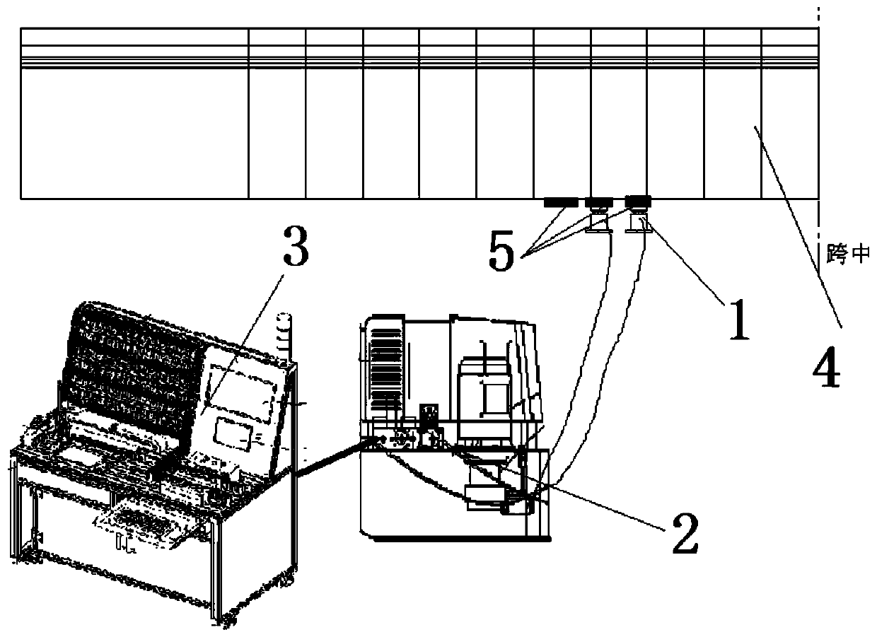
[0053] like figure 1 As shown, a synchronous jacking system for box girder formwork includes a jacking system 1, a power system 2, a control system 3, a prefabricated box girder formwork body 4 and a sensor 5, and the jacking system 1 is uniformly and longitudinally arranged on the prefabricated box girder formwork body 4. At the lower end, the power system 2 is connected to the jacking system 1 to provide power for the jacking system 1. The control system 3 is connected to the power system 2 to control the power system 2 to provide power for the jacking system 1. The sensor 5 is set in the prefabricated box The beam formwork body 4 is also connected to the control system 3 for transmitting the situation of the prefabricated box girder formwork body 4 to the control system 3. The jacking system 1 includes at least one pair of jacks 11, and the jacks 11 located in the same longitudinal row pass through the power system 2 in parallel.

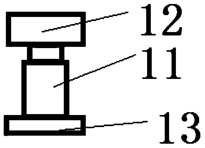
[0054] like figure 2 As shown, the jack...

Embodiment 2

[0071] like figure 1 As shown, it includes jacking system 1, power system 2, control system 3, prefabricated box girder formwork body 4 and sensor 5. 1 is connected to provide power for the jacking system 1, the control system 3 is connected to the power system 2 to control the power system 2 to provide power for the jacking system 1, and the sensor 5 is set on the prefabricated box girder formwork body 4 and connected to the control system 3 It is used to transmit the situation of the prefabricated box girder formwork body 4 to the control system 3 .

[0072] like figure 2 As shown, the jacking system 1 includes five jacks 11 uniformly arranged in each row, beams 12 and steel plates 13 , and the jacks 11 located in the same vertical row are connected in parallel through the power system 2 . The crossbeam 12 is evenly and horizontally arranged at the lower end of the box girder formwork body 4 , the jack 11 is evenly and horizontally arranged at the lower end of the crossbe...


PUM


Abstract

The invention discloses a synchronous jacking system for a prefabricated box girder template. The synchronous jacking system comprises jacking system bodies (1), a power system (2), a control system (3), a prefabricated box girder template body (4) and a sensor (5), wherein the jacking system bodies (1) are vertically and uniformly arranged at the lower end of the prefabricated box girder templatebody (4); the power system (2) is connected with the jacking system bodies (1) and used for providing power for the jacking system bodies (1); the control system (3) is connected with the power system (2) and used for controlling the power system (2) to provide power for the jacking system bodies (1); the jacking system bodies (1) comprise at least one pair of jacks (11); and the jacks (11) located in the same longitudinal row are connected in parallel through the power system (2). According to the synchronous jacking system for the prefabricated box girder template, millimeter-level intelligent pre-camber adjustment of the prefabricated box girder template is achieved.

Description

technical field [0001] The invention relates to the field of bridge construction, in particular to a prefabricated box girder formwork synchronous jacking system. Background technique [0002] The bridge synchronous jacking technology is to use rigid columns to support the beam body, sensors to provide feedback, computer-controlled hydraulic system synchronization and hydraulic jack clusters to achieve jacking under the premise of ensuring the integrity and use of the bridge structure (especially the statically indeterminate structure). . This technology can control the attitude of the beam body during the jacking process, realize multi-point synchronization, equal proportion and anti-slope jacking, and can also realize the long-term stay of the beam body in the air and the fine-tuning of the beam body posture. [0003] Patent CN88209168 discloses a hydraulic lift synchronous control device for construction. It consists of pump station, synchronizer, hydraulic press, hydra...

Claims


Application Information

Patent Timeline
Patent Type & Authority Applications(China)
IPC IPC(8): B28B1/00B28B15/00B28B17/00B66F3/46
CPCB28B1/00B28B15/00B28B17/0081B66F3/46
Inventor 苏永华班新林石龙葛凯陶晓燕尹京杨心怡朱希同
Owner RAILWAY ENG RES INST CHINA ACADEMY OF RAILWAY SCI
Why Eureka
Try Eureka