Tilting vertical take-off and landing fixed wing unmanned aerial vehicle

A vertical take-off and landing, unmanned aerial vehicle technology, applied in vertical take-off and landing aircraft, rotorcraft, unmanned aircraft, etc. problem, to achieve the effect of fast flight speed, large load capacity and small overall volume

Active Publication Date: 2019-08-30
WUHAN HAOAO AVIATION TECH CO LTD
View PDF12 Cites 3 Cited by
  • Summary
  • Abstract
  • Description
  • Claims
  • Application Information

AI Technical Summary

Problems solved by technology

[0003] At present, the UAVs on the market are large in size, relatively large in resistance when ascending, relatively small in maximum load, limited in speed and height of ascent, and limited in application

Method used


Image

  • Tilting vertical take-off and landing fixed wing unmanned aerial vehicle
  • Tilting vertical take-off and landing fixed wing unmanned aerial vehicle
  • Tilting vertical take-off and landing fixed wing unmanned aerial vehicle

Examples


Embodiment 1

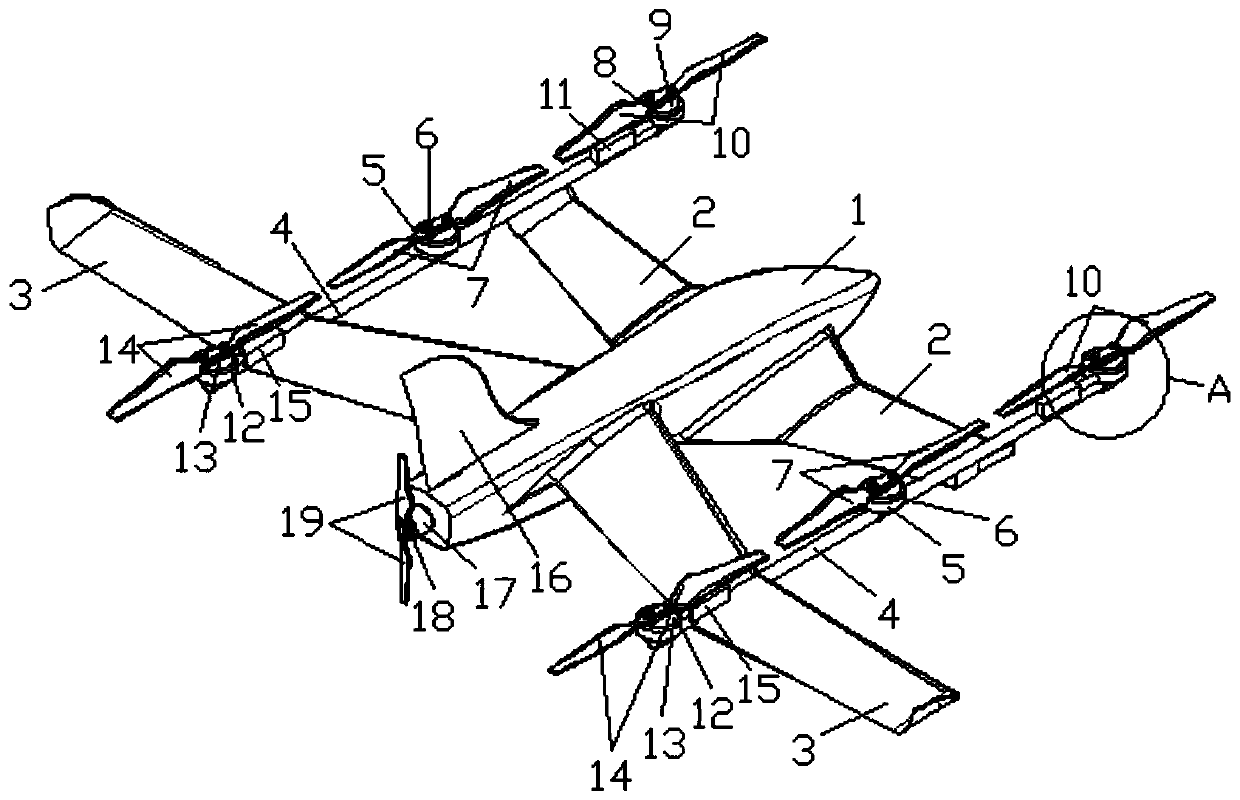
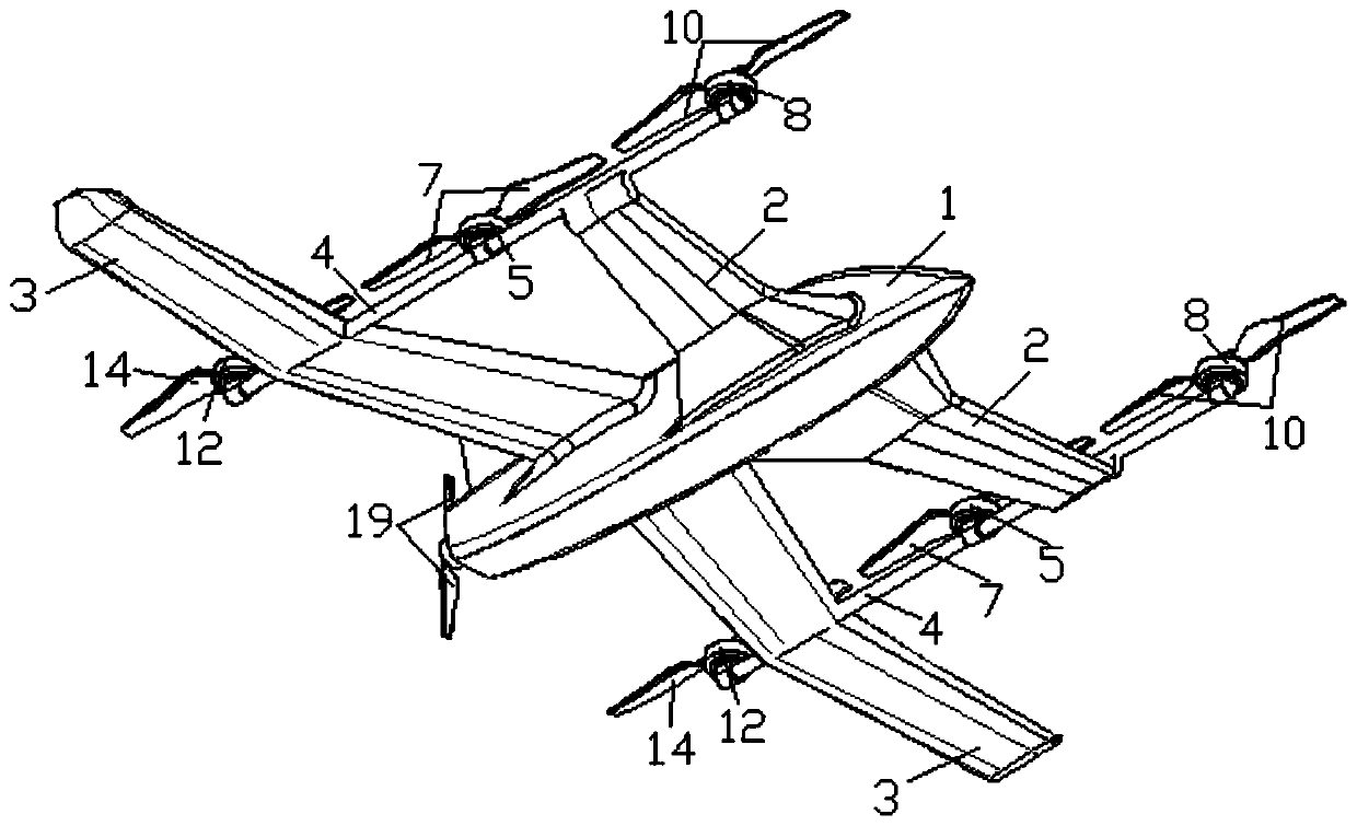
[0040] On the basis of the above-mentioned structure, in the present embodiment, the front wing mechanism and the rear wing mechanism located on the same side of the fuselage 1 are respectively connected through the connecting rod 4, and the connecting rod 4 is parallel to the fuselage 1. At this time, the length of the pincer arm 2 is Half of the length of the rear arm 3, the two ends of the connecting rod 4 are welded to the middle of the forearm 2 and the end of the rear arm 3 on the same side of the fuselage 1, and the two ends extend to the front side of the forearm 2 and the rear arm 3 respectively The rear side of the body, so that the connecting rod 4 remains parallel to the fuselage 1. The middle part of the connecting rod 4 is fixedly connected with a mid-wing mechanism, through which the lift of the UAV is improved, thereby increasing the load capacity of the UAV and improving the operational capability of the UAV.

[0041] In this embodiment, the mid-wing mechanism...

Embodiment 2

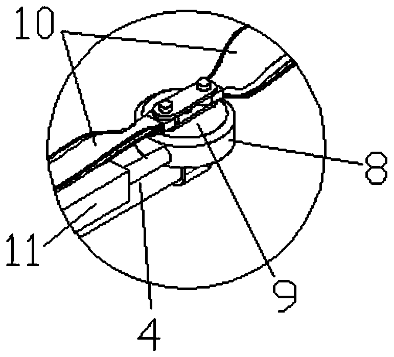
[0043] On the basis of the above structure, in the present embodiment, the front wing mechanism includes a front wing mounting base 8, a front wing motor 9 and a front wing 10, and the front wing mounting base 8 is rotatably installed on the front end of the connecting rod 4 along the front and rear direction and Positioning, the front wing motor 9 is installed on the front wing mounting seat 8, the center of the front wing mounting seat 8 is provided with a mounting groove, the front wing motor 9 is fixed in the mounting groove by bolts, and the casing of the front wing motor 9 is installed Screw holes that cooperate with the bolts are respectively provided in the groove, which is convenient for dismounting; the front wing 10 is arranged on the top of the front wing motor 9, and is fixedly connected (welded) with the driving end of the front wing motor 9; Rotate the front wing mounting base 8 to one side of it and connect and position the side wall of the connecting rod 4, and...

Embodiment 3

[0045] On the basis of Embodiment 2, in this embodiment, the front wing mechanism also includes a front wing cylinder 11 fixedly installed on the connecting rod 4, which is usually connected by bolts, and the casing of the front wing cylinder 11 and the connecting rod 4 are respectively There are screw holes matched with the bolts; the telescopic end of the front wing cylinder 11 expands and contracts along the front and rear directions, and is connected to the front wing mounting seat 8 through a hinge; when the UAV is lifted, the front wing cylinder 11 drives the front wing mounting seat 8 directions After rotating until one side of the front wing mounting base 8 is attached to the side wall of the connecting rod 4, the front wing motor 9 drives the front wing 10 to rotate at the same time to generate lift to the UAV; when the UAV is flying horizontally, the front wing cylinder 11 Drive the front wing mount 8 to rotate forward until one side of it fits the front end of the co...


PUM


Abstract

The invention relates to a tilting vertical take-off and landing fixed wing unmanned aerial vehicle which comprises a vehicle body, two forearms, two rear arms, two front wing mechanisms and two rearwing mechanisms, wherein the two forearms are fixed to the two sides of the front part of the vehicle body oppositely, and the two rear arms are fixed to the two sides of the rear part of the vehiclebody oppositely; the two front wing mechanisms are oppositely and rotatably arranged on the front sides of the two forearms and are positioned at the ends of the forearms correspondingly; and the tworear wing mechanisms are oppositely and rotatably arranged on the rear sides of the two rear arms and positioned in the middle of the rear arms. The tilting vertical take-off and landing fixed wing unmanned aerial vehicle has the beneficial effects of small size and large load capacity; meanwhile, the unmanned aerial vehicle is special in structure, large in lift-drag ratio and high in flying height; and in addition, the angles of front wings and rear wings of the unmanned aerial vehicle can be adjusted so as to provide sufficient forward power for the unmanned aerial vehicle, and the flight speed is high.

Description

technical field [0001] The invention relates to the technical field of unmanned aerial vehicles, in particular to a tiltable vertical take-off and landing fixed-wing unmanned aerial vehicle. Background technique [0002] Unmanned aircraft, referred to as "unmanned aerial vehicle", or "UAV" in English, is an unmanned aircraft that is controlled by radio remote control equipment and its own program control device, or is completely or intermittently operated autonomously by an on-board computer. Drones are often better suited for missions that are too "dumb, dirty or dangerous" than manned aircraft. [0003] At present, the UAVs on the market are large in size, relatively large in resistance when ascending, relatively small in maximum load capacity, limited in speed and height of ascent, and limited in application. Contents of the invention [0004] The technical problem to be solved by the present invention is to provide a tiltable vertical take-off and landing fixed-wing u...

Claims


Application Information

Patent Timeline
Patent Type & Authority Applications(China)
IPC IPC(8): B64C27/26B64C27/28B64C29/00
CPCB64C27/26B64C27/28B64C29/0033B64U10/10B64U10/25B64U50/19B64U30/20B64U50/13
Inventor 蔡晓东蔡昊宇
Owner WUHAN HAOAO AVIATION TECH CO LTD
Why Eureka
Try Eureka