
Double-propeller combined wing

A technology of wings and fins, applied in the field of aircraft, can solve problems such as low efficiency, unsuitable wings for heavy-load low-speed flight, and inability to generate thrust

Inactive Publication Date: 2015-12-30
FOSHAN SHENFENG AVIATION SCI & TECH
View PDF6 Cites 0 Cited by
  • Summary
  • Abstract
  • Description
  • Claims
  • Application Information

AI Technical Summary

Problems solved by technology

[0002] The traditional wing used for aircraft is a whole structure, which can only produce lift but not thrust under the action of pull or thrust generated by the engine
Moreover, the efficiency of generating lift is not high, and the wing with a small area can generate large lift only by increasing the speed.
Traditional wings are not suitable for heavy load and low speed flight

Method used


Image

  • Double-propeller combined wing
  • Double-propeller combined wing
  • Double-propeller combined wing

Examples


Embodiment Construction

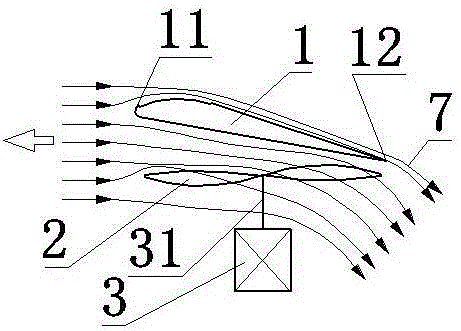
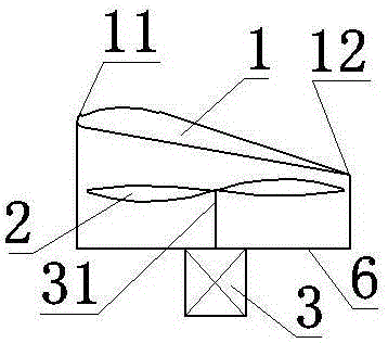
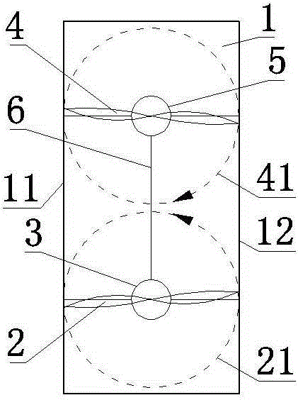
[0008] Now in conjunction with accompanying drawing, the present invention is described in detail: a kind of dual propeller compound wing, comprises wing blade 1, first propeller 2, first electric motor 3, second propeller 4 and second electric motor 5. The first propeller 2 and the second propeller 4 are at the same height. The first motor 3 is located below the first propeller 2, and the first propeller 2 is connected to the first motor output shaft 31; the second motor 5 is located below the second propeller 4, and the second propeller 4 is connected to the second motor output shaft 51; The first motor 3 and the second motor 5 are made of lithium batteries. The structural parameters of the first propeller 2 and the second propeller 4 are the same, and the direction of rotation is opposite. The power and rotational speed of the first motor 3 and the second motor 5 are the same. The first motor 3 and the second motor 5 are connected to the vane 1 through a bracket 6 . The ...


PUM


Abstract

The invention discloses a double-propeller combined wing and belongs to the technical field of aircrafts. The double-propeller combined wing comprises a wing panel, a first propeller, a first electric motor, a second propeller and a second electric motor, wherein the wing panel is located above the first propeller and the second propeller; the leading edge of the wing panel is higher than the tailing edge of the wing panel; the downward projection of the wing panel can completely cover the first propeller and the second propeller; the rotary planes of the first propeller and the second propeller are located in the horizontal direction or slightly inclined forwards and downwards; the first electric motor drives the first propeller to rotate, and the second electric motor drives the second propeller to rotate; the double-propeller combined wing moves forwards, coming airflow flows to the rear and lower part of the double-propeller combined wing at an increasing speed under the joint action of the wing panel, the first propeller and the second propeller, and upward lift force and forward push force are generated. During forward movement, the wing bears smaller resistance, the efficiency is higher, the lift drag is higher, and the double-propeller combined wing is suitable for a heavy-load aircraft flying at a low speed.

Description

technical field [0001] The utility model relates to a dual-blade compound wing, which belongs to the technical field of aircraft, and in particular relates to a compound wing. Background technique [0002] The traditional wing used for aircraft is a monolithic structure, which can only produce lift but not thrust under the action of pulling force or thrust produced by the engine. And the efficiency of generating lift is not high, and the less wing of area produces big lift and just can realize by increasing speed. Traditional airfoils are not suitable for low-speed flight with heavy loads. Contents of the invention [0003] The purpose of the present invention is to overcome the above-mentioned deficiency of traditional wing, invent a kind of double paddle composite wing that can produce both lift and thrust. [0004] A dual-screw compound wing includes blades, a first propeller, a first motor, a second propeller and a second motor. The first propeller and the second pr...

Claims


Application Information

Patent Timeline
Patent Type & Authority Applications(China)
IPC IPC(8): B64C27/26B64C27/22
Inventor 王志成
Owner FOSHAN SHENFENG AVIATION SCI & TECH
Learn More