
Road-rail co-layer mixed-beam suspension cable-stayed cooperation bridge

A hybrid beam and cooperative bridge technology, applied in suspension bridges, cable-stayed bridges, bridges, etc., can solve the problems of unsuitable bridges, small axial force of main beams, good structural stability, etc., and meet the requirements of railway track shape and position deformation. , The overall rigidity of the structure is large, and the overall rigidity of the main beam is large.

Pending Publication Date: 2019-08-30
CHINA RAILWAY SIYUAN SURVEY & DESIGN GRP
View PDF0 Cites 5 Cited by
  • Summary
  • Abstract
  • Description
  • Claims
  • Application Information

AI Technical Summary

Problems solved by technology

The advantages of cable-stayed bridges are high overall rigidity, simple structure, convenient construction, and relatively low cost. However, as the span increases, the bridge deck girder bears a huge axial force, and the stability is difficult to control. Large, the height of the bridge tower is high, controlled by the bearing capacity of the concrete material, resulting in a multiple increase in the structural volume, and the creep is also difficult to control; in addition, due to the layout of the highway and railway on the same floor, the width of the bridge deck is greatly increased, and the lateral force is relatively large , to improve the stability of the main beam structure
[0003] The suspension bridge is also a bridge structure widely used at present. The advantages of the suspension bridge are large spanning capacity, low bridge tower, small axial force of the main girder, and good structural stability; but it is a flexible structure with low structural rigidity. Not applicable to bridges with highway and railway on the same floor

Method used


Image

  • Road-rail co-layer mixed-beam suspension cable-stayed cooperation bridge
  • Road-rail co-layer mixed-beam suspension cable-stayed cooperation bridge
  • Road-rail co-layer mixed-beam suspension cable-stayed cooperation bridge

Examples


Embodiment Construction

[0022] The following will clearly and completely describe the technical solutions in the embodiments of the present invention with reference to the accompanying drawings in the embodiments of the present invention. Obviously, the described embodiments are only some, not all, embodiments of the present invention. Based on the embodiments of the present invention, all other embodiments obtained by persons of ordinary skill in the art without making creative efforts belong to the protection scope of the present invention.

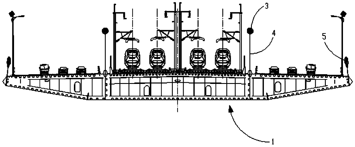
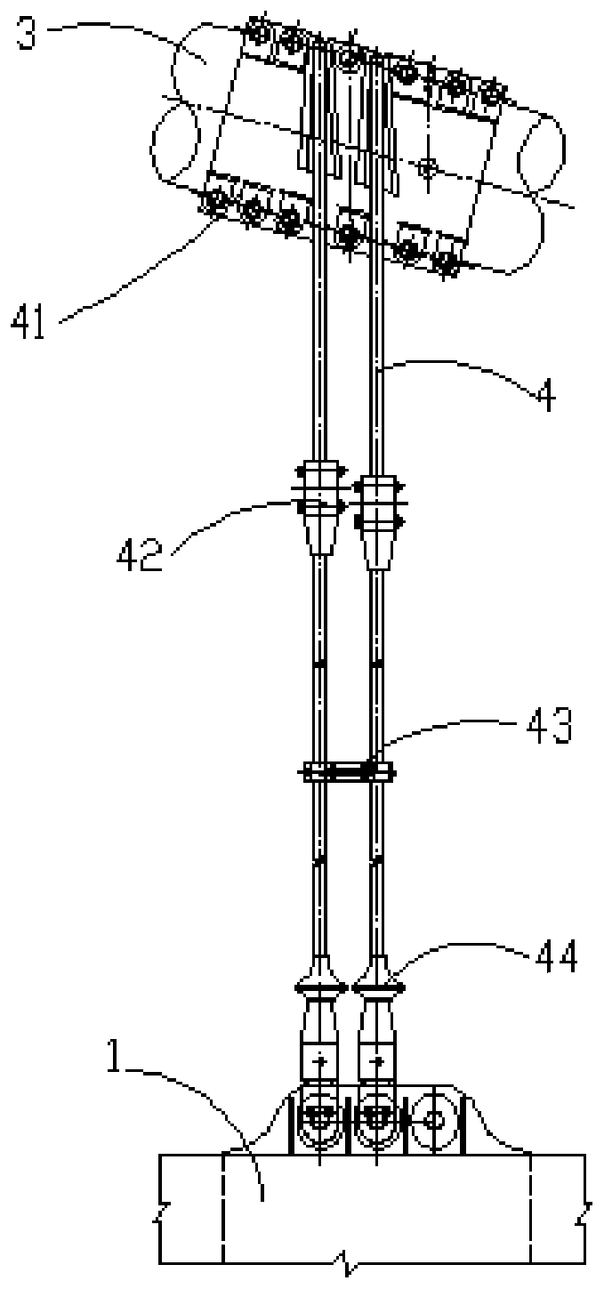
[0023] Such as figure 1 , the embodiment of the present invention provides a road-rail mixed girder suspension cable-stayed cooperative bridge on the same floor, comprising a main girder 1 and at least two bridge towers 2 sequentially arranged along the bridge direction, and the main girder 1 is arranged on the same floor. The road bridge deck and the railway bridge deck are connected by a main cable 3 between two adjacent bridge towers 2, and the main cable 3...


PUM


Abstract

The invention relates to a road-rail co-layer mixed-beam suspension cable-stayed cooperation bridge. The bridge comprises a main beam and at least two bridge towers, wherein the two bridge towers aresequentially arranged along the bridge direction, a road bridge deck and an rail bridge deck are arranged on the main beam in the same layer, the two adjacent bridge towers are connected through a main cable, and the main cable is connected with main beam bodies below through a sling; and each bridge tower is connected with main beam bodies on the two sides through an stay cable. According to theroad-rail co-layer mixed-beam suspension cable-stayed cooperation bridge, a suspension structure of the main cable plus the sling and a cable-stay structure of the stay cable are combined, the advantages of a suspension bridge and a cable-stayed bridge are brought into full play, thus effective improving the rigidity of 1 / 4 of the span and span area structure; in addition, the main beam is large in overall rigidity and reasonable in stress, so that the span of a bridge can be improved to 1600 m, the overall rigidity of the structure is large, and accordingly requirements of railway track shapedeformation can be fully met.

Description

technical field [0001] The invention belongs to the technical field of bridge engineering, and in particular relates to a suspension and cable-stayed cooperative bridge with mixed girders on the same floor for highway and railway. Background technique [0002] Most of the bridges built jointly by road and railway adopt layered deck layout. With the continuous development and technological progress of highway and railway construction, bridges arranged on the same layer by road and rail are also applied. These bridges on the same layer of road and rail basically use cable-stayed bridges The structure of the bridge. The advantages of cable-stayed bridges are high overall rigidity, simple structure, convenient construction, and relatively low cost. However, as the span increases, the bridge deck girder bears a huge axial force, and the stability is difficult to control. Large, the height of the bridge tower is high, controlled by the bearing capacity of the concrete material, r...

Claims


Application Information

Patent Timeline
IPC IPC(8): E01D11/02E01D11/04E01D19/12
CPCE01D11/02E01D11/04E01D19/125
Inventor 文望青严爱国李桂林王新国史娣严定国张晓江王鹏宇曾甲华杨得旺左武李靓亮周继崔苗苗李的平王志平张杰殷鹏程吴孟畅
Owner CHINA RAILWAY SIYUAN SURVEY & DESIGN GRP
Learn More