
Display apparatus

A display device and display technology, which is applied in the direction of circuit devices, battery circuit devices, static indicators, etc., can solve the problems of slow solar cells, etc.

Active Publication Date: 2019-08-30
PURELIFI
View PDF10 Cites 7 Cited by
  • Summary
  • Abstract
  • Description
  • Claims
  • Application Information

AI Technical Summary

Problems solved by technology

Solar cells may be too slow for the high data rates used in modern wireless communication standards, which may limit the use of transparent solar cells as OWC detectors

Method used


Image

  • Display apparatus
  • Display apparatus
  • Display apparatus

Examples


Embodiment Construction

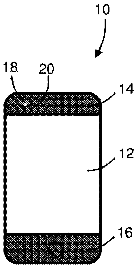
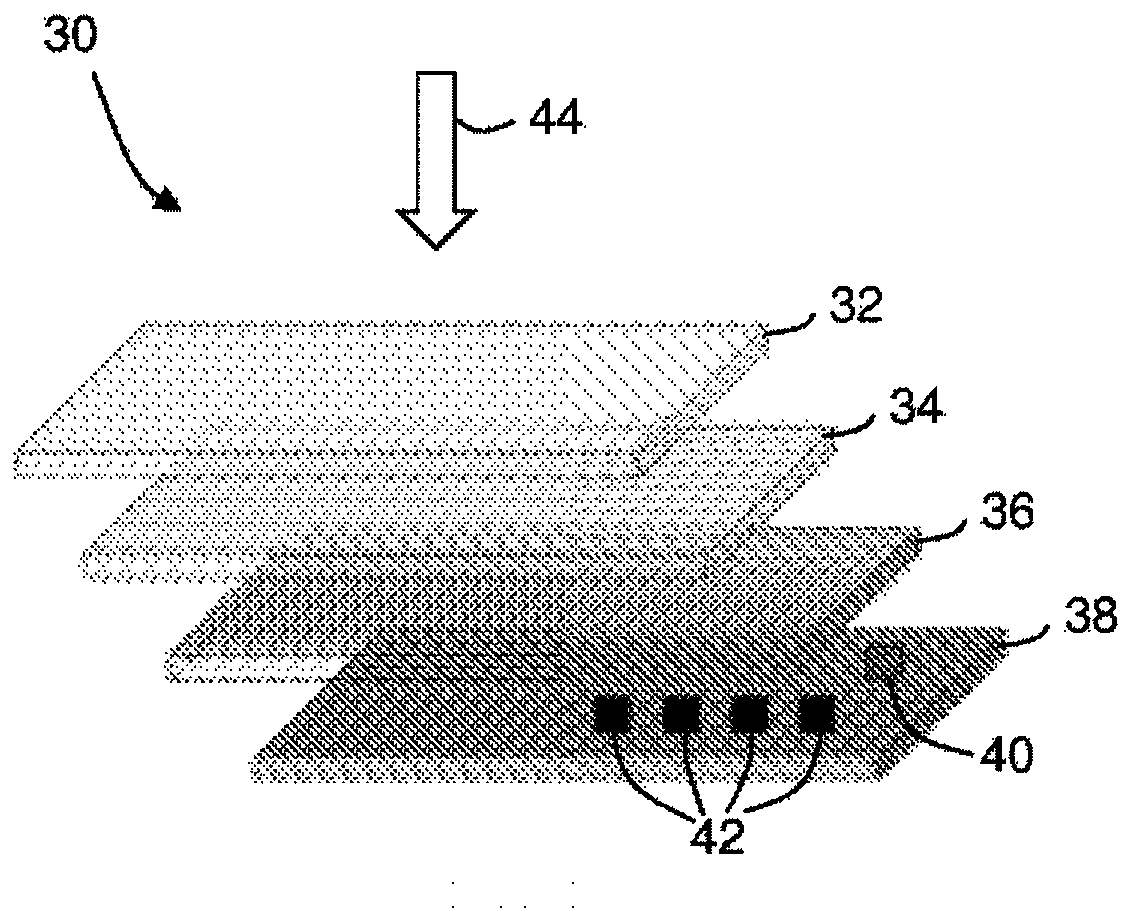
[0142] figure 2 It is a schematic diagram of the LIFI support screen 30 according to an embodiment. The LIFI support screen 30 can be located in the display screen area of ​​the mobile phone or another device. For example, the LIFI support screen can be used in another mobile computing device, such as a tablet or laptop, or can be used in a desktop computer. LIFI support screen 30 can include any device having a display screen, for example, including in a household appliance or point of sale. The LIFI support screen 30 can be referred to as a display device.

[0143] The LIFI support screen 30 includes a plurality of substantially flat layers. figure 2 The layers observed from the side are shown in a decomposition diagram. These layers are expressed as the layer that is closest to the front surface of the mobile phone is located figure 2 top of. Although these layers are flat and rectangular in this embodiment, in other embodiments, these layers may have any suitable shape.

[01...


PUM


Abstract

A display apparatus comprises an at least partially transparent display, the display configured to generate light to form an image for display to a user positioned in front of the display, and at least one light-transmitting and / or light-receiving device positioned behind the display, wherein the at least one light-transmitting and / or light-receiving device is configured to transmit and / or receivelight through at least part of the display, wherein the at least one light-transmitting and / or light-receiving device comprises or forms part of an optical wireless communications (OWC) apparatus configured to transmit and / or receive the light through the at least part of the display.

Description

Technical field [0001] The present invention relates to a display device for an electronic device having at least one integrated photoelectric assembly, for example, a display device for an electronic device having an integrated optical wireless communication transceiver. Background technique [0002] Many electro-optical components may require light receiving and / or light transmission to achieve their operation. Such components can include, but are not limited to, optical wireless communication (OWC) transceivers, light-based motion detectors, cameras, optical sensors, solar cells, proximity sensors or flashlights. [0003] Light receiving and / or light transmission is required to implement the electro-optical components thereof, which may require the path between the optical detector or transmitter and the external environment. [0004] The visible light captured by the camera's sensor may require the path between the captured image and the sensor to substantially hinder. In...

Claims


Application Information

Patent Timeline
Patent Type & Authority Applications(China)
IPC IPC(8): G06T1/00G09G3/3208H01L27/32H04B10/11
CPCG06T1/00G09G3/3208H04B10/11G06F1/1637Y02E10/50Y02E70/30H10K59/60H10K59/121H10K59/00H02S40/38G09G3/32G09G5/10G09G2360/144G09G2370/16G09G2370/18H02J7/35H04B10/116H04M1/0266H04M2201/38
Inventor 多布罗斯拉夫·佐内夫伊斯特万·菲利普·伯纳德·乔亚吉邓肯·约翰·威廉·沃克伊凡·阿尔夫·卡尔松阿图尔·维托尔德·维乔雷克
Owner PURELIFI
Learn More