
Rotor and motor using same

A technology of rotor and rotor core, which is applied in the direction of magnetic circuit rotating parts, electrical components, electromechanical devices, etc., can solve the problems of uneven magnetic flux and magnetic imbalance, and achieve the effect of reducing torque fluctuation and improving magnetic imbalance

Inactive Publication Date: 2019-09-03
NIDEC CORP
View PDF4 Cites 0 Cited by
  • Summary
  • Abstract
  • Description
  • Claims
  • Application Information

AI Technical Summary

Problems solved by technology

Therefore, depending on the shape of the salient pole portion of the rotor core, the magnetic flux may flow unevenly with respect to the plurality of salient pole portions.
That is, the direction and amount of magnetic flux flowing in the salient pole portion of the rotor core depend on the shape of the above salient pole portion, so a magnetic imbalance occurs in the rotor

Method used


Image

  • Rotor and motor using same
  • Rotor and motor using same
  • Rotor and motor using same

Examples


Embodiment Construction

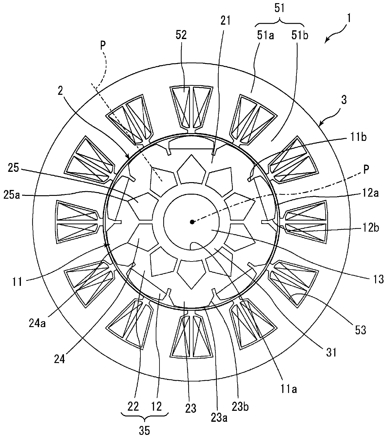
[0025] Hereinafter, embodiments of the present invention will be described in detail with reference to the drawings. In addition, the same code|symbol is attached|subjected to the same or corresponding part in a figure, and the description is not repeated. In addition, the dimensions of the components in the drawings do not fully represent the dimensions of the actual components, the dimensional ratios of the components, and the like.

[0026] In addition, in the following description, the direction parallel to the central axis of the rotor is referred to as "axial direction", the direction perpendicular to the central axis is referred to as "radial direction", and the direction along an arc centered on the central axis is referred to as The direction is called "circumferential". However, the definition of this direction is not intended to limit the orientation when using the rotor and motor of the present invention.

[0027] (the whole frame)

[0028] exist figure 1 A sch...


PUM


Abstract

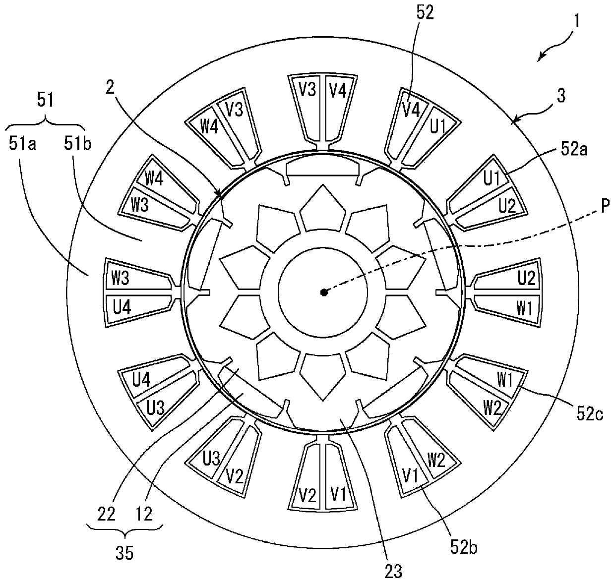
A rotor (2) is equipped with: a cylindrical rotor core (11) that is provided with a plurality of salient pole portions (23) protruding in the radial direction, and extends along the central axis (P);and a plurality of magnetic pole portions (35) that are provided with, upon the outer peripheral surface of the rotor core (11) or in the interior of the same in the radial direction, rotor magnets (12) disposed in a manner alternating with the salient pole portions (23) in the circumferential direction of the rotor core (11). The salient pole portions (23) and the magnetic pole portions (35) arethe magnetic poles of the rotor (2). In a cross-section orthogonal to the central axis (P), the salient pole portions (23) are each provided with, on at least one end in the circumferential direction,a salient pole taper section (23b) in which the outer peripheral surface (23a) of the salient pole portion (23) inclines in a straight line inward in the radial direction, said incline tapering fromthe center to the outer side of the salient pole portion (23) in the circumferential direction.

Description

technical field [0001] The present invention relates to a rotor and a motor using the same. Background technique [0002] Conventionally, as a rotor used in a motor, a structure including a rotor core and a rotor magnet is known. Since the price of rotor magnets has risen in recent years along with the rise in the price of rare earths, studies on the structure of rotors that reduce the amount of rotor magnets used are being conducted. As a motor in which the amount of rotor magnets used in the rotor is reduced, for example, as disclosed in Patent Document 1, an alternate-type motor (consequent-type motor) using a part of the rotor core as a dummy pole has been proposed. [0003] In general, in an alternating motor in which a part of the rotor core is used as a dummy pole, there is a greater imbalance in the magnetic properties of each magnetic pole than in a normal motor in which all the magnetic poles are composed of rotor magnets. That is, in the rotor of an alternating ...

Claims


Application Information

Patent Timeline
Patent Type & Authority Applications(China)
IPC IPC(8): H02K1/27
CPCH02K1/27H02K1/276H02K1/223H02K1/274
Inventor 上田智哉
Owner NIDEC CORP
Learn More