A compound fertilizer mixing and stirring equipment

A technology for mixing and mixing fertilizers, which is applied to mixers, mixer accessories, mixers with rotary mixing devices, etc., can solve the problem of inability to control the mixing ratio of two fertilizer raw materials.

Active Publication Date: 2021-08-06
山东润禾钾盐科技有限公司
View PDF14 Cites 0 Cited by
  • Summary
  • Abstract
  • Description
  • Claims
  • Application Information

AI Technical Summary

Problems solved by technology

But this invention can't realize the mixing ratio of controlling the two kinds of fertilizer raw materials

Method used


Image

  • A compound fertilizer mixing and stirring equipment
  • A compound fertilizer mixing and stirring equipment
  • A compound fertilizer mixing and stirring equipment

Examples


specific Embodiment approach 1

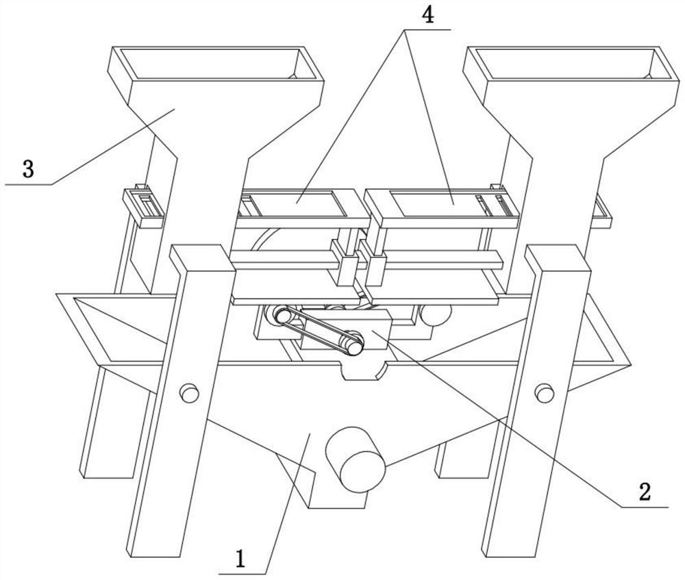
[0028] Combine below Figure 1-9 Describe this embodiment, the present invention relates to a kind of mixing equipment, more specifically a kind of compound fertilizer mixing and stirring equipment, including mixer 1, opening and closing control mechanism 2, fertilizer box 3 and opening and closing door 4, the present invention can By setting the area of ​​different blanking holes 4-6 on the two blanking plates 4-5, the mixing ratio of the two fertilizer raw materials can be controlled, and when mixing is not required, the two bottom covers 4-1 are closed , at this time the stirring shaft 1-7 will also stop the stirring operation.

[0029] The opening and closing control mechanism 2 is fixedly connected to the upper end of the mixer 1, the rear end of the opening and closing control mechanism 2 is engaged with the mixer 1 for transmission, the fertilizer box 3 is fixedly connected to the upper end of the mixer 1, and the opening and closing control mechanism 2 is located at th...

specific Embodiment approach 2

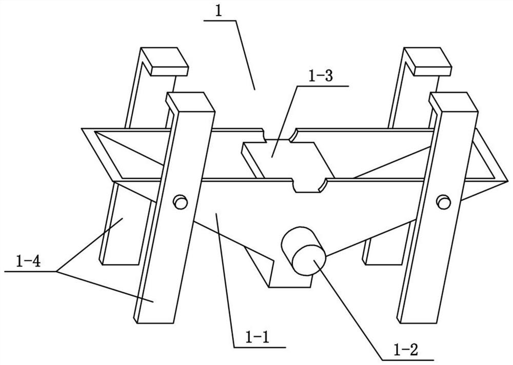
[0031] Combine below Figure 1-9 To illustrate this embodiment, the mixer 1 includes a triangular funnel 1-1, a motor I1-2, a middle support plate 1-3, a support rod 1-4, a discharge port 1-5, a pinion 1-6, a stirring The shaft 1-7 and the stirring rod 1-8, the triangular funnel 1-1 is an inverted triangular container, the lower end of the triangular funnel 1-1 is provided with a discharge port 1-5, and the motor I1-2 is fixedly connected to the bottom of the triangular funnel 1-1 At the front end, the output shaft of the motor I1-2 is fixedly connected with a stirring shaft 1-7, and the stirring shaft 1-7 is provided with a plurality of stirring rods 1-8, and the stirring shaft 1-7 and a plurality of stirring rods 1-8 are located at the outlet Above the feed port 1-5, the rear end of the stirring shaft 1-7 is fixedly connected with a pinion 1-6, the front and rear ends of the left end of the triangular funnel 1-1 are fixedly connected with a support rod 1-4, and the triangula...

specific Embodiment approach 3

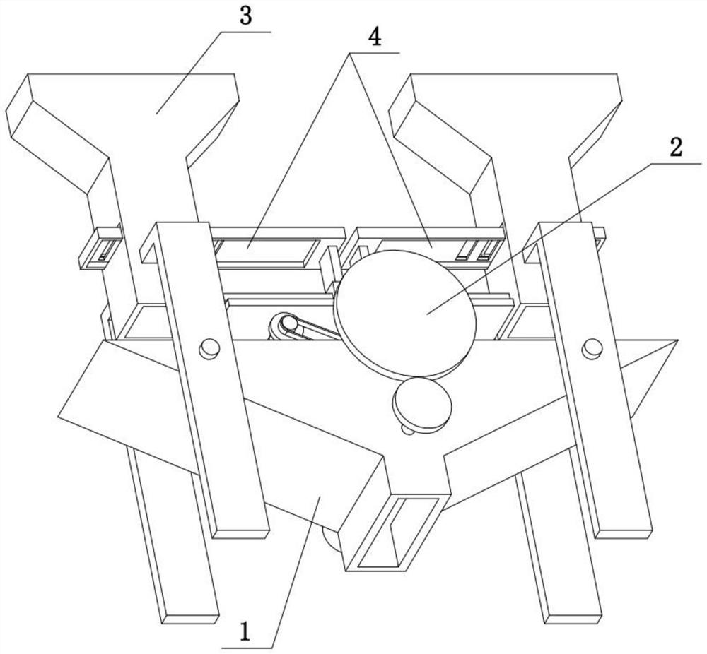
[0033] Combine below Figure 1-9To illustrate this embodiment, the opening and closing control mechanism 2 includes a middle block 2-1, a side frame 2-2, a right friction wheel 2-3, a right shaft 2-4, a right pulley 2-5, a large gear 2-6, Rear axle rod 2-7, left friction wheel 2-8, left shaft 2-9, left pulley 2-10, middle pulley 2-11 and middle shaft 2-12, the middle end of middle piece 2-1 rotates and is connected with middle Axle 2-12, the front and rear ends of central axis 2-12 are all fixedly connected with middle pulley 2-11, the left and right ends of middle block 2-1 are all fixedly connected with side frame 2-2, the side frame 2-2 of right end The upper rotation is connected with the right shaft 2-4, and the front and rear ends of the right shaft 2-4 are fixedly connected with the right friction wheel 2-3, and the right friction wheel 2-3 at the rear end is fixedly connected with the right belt pulley 2-5, the right The belt pulley 2-5 and the middle pulley 2-11 at t...


PUM


Abstract

The present invention relates to a mixing equipment, more specifically a compound fertilizer mixing equipment, including a mixer, an opening and closing control mechanism, a fertilizer box and an opening and closing door. The method of different areas of the falling holes, so as to realize the control of the mixing ratio of the two fertilizer raw materials. The opening and closing control mechanism is fixedly connected to the upper end of the mixer, the rear end of the opening and closing control mechanism is engaged with the mixer for transmission, the fertilizer box is fixedly connected to the upper end of the mixer, the opening and closing control mechanism is located at the lower end of the fertilizer box, and the opening and closing door Two opening and closing doors are arranged on the left and the right, and both opening and closing doors are slidingly connected with the fertilizer box, and the two opening and closing doors are respectively slidingly connected with the left and right ends of the fertilizer box.

Description

technical field [0001] The invention relates to a stirring device, in particular to a compound fertilizer mixing and stirring device. Background technique [0002] The application number is CN201610766385.1, which discloses a mobile small-scale fertilizer mixing and stirring device. The invention discloses a movable small-scale fertilizer mixing and stirring device, which includes a storage chamber, a heating controller, a stirring controller, a bracket and a base. The top of the storage chamber is provided with a feed port, the bottom of the storage chamber is provided with a support, the end of the support is provided on the base, the bottom of the base is provided with a plurality of rollers, and one side of the storage chamber is provided with Stirring controller, the inside of the stirring controller is provided with a motor, and the motor is connected with a stirring rod for rotation, and the stirring rod is arranged in the material storage cavity, and a stirring knife...

Claims


Application Information

Patent Timeline
Patent Type & Authority Patents(China)
IPC IPC(8): B01F7/04B01F15/02B01F15/04
CPCB01F27/191B01F27/70B01F35/71B01F35/80B01F2101/32
Inventor 寇富强
Owner 山东润禾钾盐科技有限公司
Why Eureka
Try Eureka