Communication antenna mounting support and power communication shared tower with same

A technology for installing brackets and communication antennas, which is applied to antenna supports/installation devices, towers, building types, etc., and can solve the problems of increasing lifting equipment, inconvenient installation, and increasing engineering investment, saving construction costs and avoiding power outages. Effect

Active Publication Date: 2019-09-06
STATE GRID CORP OF CHINA +1
View PDF11 Cites 1 Cited by
  • Summary
  • Abstract
  • Description
  • Claims
  • Application Information

AI Technical Summary

Problems solved by technology

The shared iron tower sets the antenna on the top of the iron tower. In order to meet its installation needs, cumbersome lifting equipment is added, which increases engineering investment. The antenna cannot be folded and is inconvenient to install.

Method used


Image

  • Communication antenna mounting support and power communication shared tower with same
  • Communication antenna mounting support and power communication shared tower with same
  • Communication antenna mounting support and power communication shared tower with same

Examples


Embodiment 1

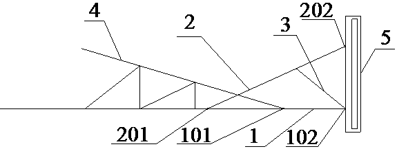
[0032] refer to figure 1 , a communication antenna mounting bracket 10, including a horizontal support 1, a bracket brace 2 and a reverse brace 3, the first end 101 of the horizontal support 1 is connected to the end of the cross arm 4, and the second end 102 is connected to the end of the antenna 5 The lower part is connected, the first end 201 of the bracket brace 2 is connected to the lower end surface of the cross arm 4, and the second end 202 is connected to the upper part of the antenna 5, and the reverse brace 3 is arranged between the horizontal support 1 and the bracket brace 2.

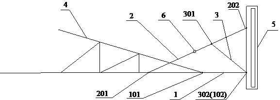
[0033] refer to figure 2 , the hinged node 6 is set on the bracket brace 2, and during the folding process of the bracket brace 2, the first end 301 of the reverse brace 3 moves in the lower end surface of the bracket brace 2, and the second end 301 of the reverse brace 3 End 302 is pivoted relative to the second end of the horizontal brace. The design of the hinge node 6 enables the supp...

Embodiment 2

[0039] refer to Figure 4-5 , an electric power communication shared iron tower, including an iron tower body 8, a cross arm 4 arranged on the iron tower body 8, and a power transmission wire 9 suspended on the cross arm 4, and also includes a communication antenna mounting bracket 10, and the communication antenna mounting bracket 10 is arranged on The outer side of the end of the cross arm 4.

[0040] The cross arms 4 are symmetrically arranged on both sides of the iron tower body 8 from top to bottom, Figure 4-5 In the specific embodiment shown in , the cross arm has three layers, and the power transmission wires are hung on both sides of each layer of cross arms, and the A-phase power transmission wire 901, the B-phase power transmission wire 902 and the C-phase power transmission wire 903 are hung in sequence from top to bottom. .

[0041] The antenna 5 is installed on the communication antenna mounting bracket 10, and the clearance distance between the antenna 5 and t...


PUM


Abstract

The invention provides a communication antenna mounting support and a power communication shared tower with the same, and belongs to the technical field of power and communication engineering. The communication antenna mounting support comprises a horizontal support, support diagonal bracings and reverse diagonal bracings; the first end of the horizontal support is connected with the end of a cross arm, and the second end of the horizontal support is connected with the lower part of an antenna; the first ends of the support diagonal bracings are connected with the lower end face of the cross arm, and the second ends of the support diagonal bracings are connected with the upper part of the antenna; and the reverse diagonal bracings are arranged between the horizontal support and the supportdiagonal bracings. Through connecting cooperation of the horizontal support, the support diagonal bracings and the reverse diagonal bracings, the communication antenna is mounted on the power communication shared tower without being sheltered and can also be folded up, and the phenomenon that a power transmission line is forced to be subjected to a power failure due to antenna overhauling is avoided.

Description

technical field [0001] The invention belongs to the technical field of electric power and communication engineering, and in particular relates to a communication antenna installation bracket and a power communication shared iron tower with the bracket. Background technique [0002] The power communication sharing tower is to install communication equipment on the power tower to realize the sharing of tower resources. In order to ensure the safe and reliable operation of the power line, and at the same time avoid the communication signal being affected by the shielding of the tower components and guide (ground) wires, the previous communication antennas were installed more The position of the iron tower body below the power line (that is, below the cross-arm of the conductor), while maintaining a sufficient safe distance from the power line, realizes that the antenna transmission direction is not blocked; although the previous antenna installation position meets the requiremen...

Claims


Application Information

Patent Timeline
IPC IPC(8): E04H12/08E04H12/24H01Q1/12
CPCE04H12/08E04H12/24H01Q1/12
Inventor 齐道坤刘湘莅郭新菊席小娟路晓军梁晟杨敏唐旻郭静赵志虎景川
Owner STATE GRID CORP OF CHINA
Why Eureka
Try Eureka