Wind inlet ring, wind wheel, draught fan structure and extractor hood

A technology for range hoods and air inlet rings, which is applied in the fields of air inlet rings, wind wheels, fan structures and range hoods, and can solve problems such as reducing the air intake area, reducing effective air volume, and obstructing gas

Pending Publication Date: 2019-09-06
VATTI CORP LTD
View PDF0 Cites 0 Cited by
  • Summary
  • Abstract
  • Description
  • Claims
  • Application Information

AI Technical Summary

Problems solved by technology

[0003] As the core component of the range hood, the fan system plays a decisive role in its performance; the traditional fan system includes a volute, a wind wheel, an air intake ring and a motor. The wheel is installed on the output shaft of the motor, and the air inlet ring is installed at the air inlet of the volute; when the smoke is sucked and exhausted, the airflow flows in from the outside of the volute through the air inlet ring, and then the flow direction of the airflow changes from axial to radial. It flows out through the air outlet of the wind wheel and volute; because there is a certain gap between the inlet of the centrifugal fan fan wheel and the air inlet ring, part of the gas flowing out of the wind wheel will leak back to the inlet of the wind wheel through the gap, reducing the effective air volume, and The backflow gas will hinder the normal flow of gas, reduce the intake area, generate vortex, reduce the efficiency, and generate unnecessary noise

Method used


Image

  • Wind inlet ring, wind wheel, draught fan structure and extractor hood
  • Wind inlet ring, wind wheel, draught fan structure and extractor hood
  • Wind inlet ring, wind wheel, draught fan structure and extractor hood

Examples


Embodiment Construction

[0035] In order to make the object, technical solution and advantages of the present invention clearer, the present invention will be further described in detail below in conjunction with the accompanying drawings and embodiments. It should be understood that the specific embodiments described here are only used to explain the present invention, not to limit the present invention.

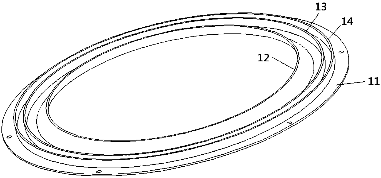
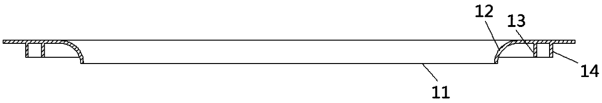
[0036] Embodiment 1 of the present invention provides an air intake ring, such as Figure 1-2 As shown, it includes the air intake ring body 11, the first flange 12, the second flange 13 and the third flange 14, the first flange 12, the second flange 13 and the third flange 14 from the inside to the outside They are sequentially arranged on the wind inlet ring body 11, and an annular groove for matching with the end surface of the wind wheel is formed between the second flange 13 and the third flange 14;

[0037] In this way, an annular groove for matching with the end surface of the wind wheel is...


PUM


Abstract

The invention discloses a wind inlet ring. The wind inlet ring comprises a wind inlet ring body, a first convex edge, a second convex edge and a third convex edge, wherein the first convex edge, the second convex edge and the third convex edge are sequentially arranged on the wind inlet ring body from inside to outside; and an annular groove which fits the end surface of a wind wheel is formed between the second convex edge and the third convex edge. The invention also discloses the wind wheel, a draught fan structure and an extractor hood. According to the wind inlet ring, the annular grooveformed between the second convex edge and the third convex edge is formed in the wind inlet ring; the main end surface of the wind wheel is outwards bent to form a side end surface, and the side end surface is matched with the annular groove to form a labyrinth sealing channel; throttling effect is realized while wind flows through the twisty labyrinth channel, and thus the purpose of resisting leaking is achieved.

Description

technical field [0001] The invention belongs to the technical field of kitchen appliances, and in particular relates to an air intake ring, a wind wheel, a fan structure and a range hood. Background technique [0002] With the development of Chinese cities, range hoods have become more and more popular, and people's requirements for the extraction capacity of range hoods have become more and more stringent. [0003] As the core component of the range hood, the fan system plays a decisive role in its performance; the traditional fan system includes a volute, a wind wheel, an air intake ring and a motor. The wheel is installed on the output shaft of the motor, and the air inlet ring is installed at the air inlet of the volute; when the smoke is sucked and exhausted, the airflow flows in from the outside of the volute through the air inlet ring, and then the flow direction of the airflow changes from axial to radial. It flows out through the air outlet of the wind wheel and vo...

Claims


Application Information

Patent Timeline
Patent Type & Authority Applications(China)
IPC IPC(8): F24C15/20
CPCF24C15/20
Inventor 李永波李智怀潘叶江
Owner VATTI CORP LTD
Why Eureka
Try Eureka