Automobile threshold verification device, system and method
A verification device and threshold technology, applied in measurement devices, vehicle testing, instruments, etc., can solve problems such as prolonging the development cycle of the whole vehicle, unfavorable real-time problems, and increasing R&D costs, so as to improve R&D efficiency, save R&D costs, enhance The effect of vehicle comfort
- Summary
- Abstract
- Description
- Claims
- Application Information
AI Technical Summary
Problems solved by technology
Method used
Image
Examples
Embodiment 1
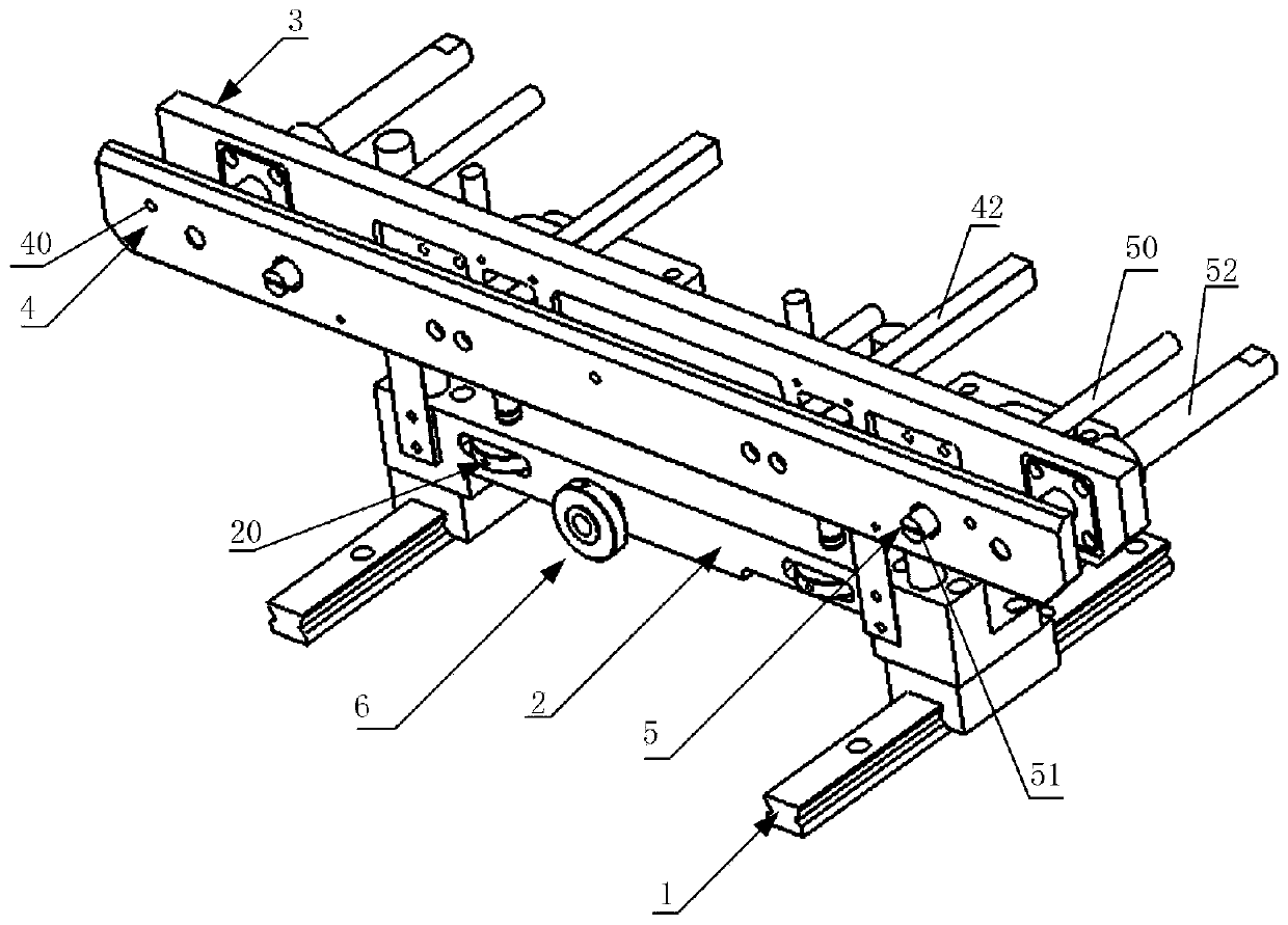
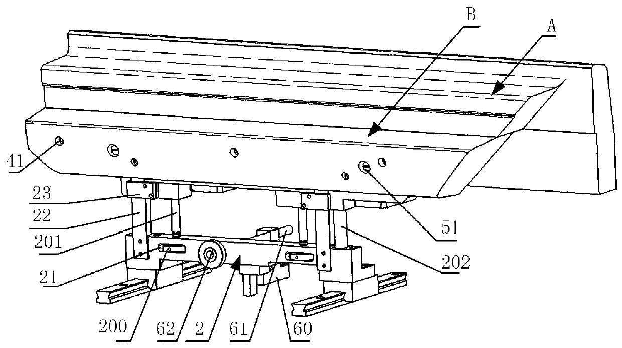
[0053] see figure 1 As shown, the present embodiment provides a vehicle threshold verification device, which includes at least one slide rail 1, a slide seat 2, a first mounting plate 3, a second mounting plate 4 and a first driving member 5; meanwhile, see figure 2 As shown, the first installation plate 3 is used to install one of the door sill bead guard plate profile A and the side outer enclosure profile B, and the second installation plate 4 is used to install the door sill bead guard plate profile A and the side outer enclosure profile another in B; see figure 1 As shown, in this embodiment, there are two slide rails 1, and the two ends of the slide seat 2 are respectively slidably assembled on the two slide rails 1. With the help of the slide rail 1, the slide seat 2 can move along the slide rail 1 to move back and forth, so as to adjust the position of the door sill bead guard plate profile A and the side outer surrounding profile B; the sliding seat 2 is provided wi...
Embodiment 2
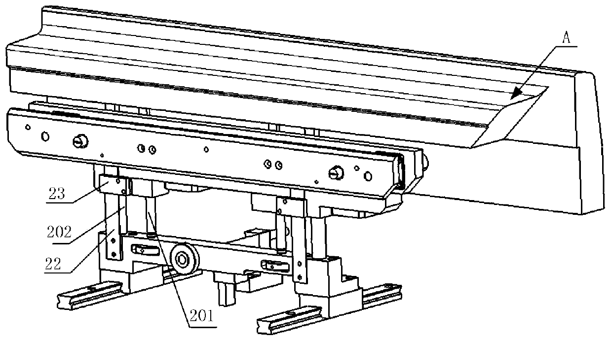
[0055] see figure 2 and image 3As shown, the difference between this embodiment and Embodiment 1 is that: a housing chamber 21 is opened in the slide seat 2, the first mounting plate 3 has a first threaded through hole (not marked in the figure), and the lifting device 20 includes a first hand wheel 200, the first screw rod 201 and the first guide rail 202, wherein the first hand wheel 200 is partly accommodated in the housing cavity 21; the first screw rod 201 is vertically arranged, its bottom end is connected with the first hand wheel 200, and the top end passes through the sliding The upper surface of the seat 2 is screwed to the first threaded through hole; the first guide rail 202 is arranged vertically, its bottom end is connected with the sliding seat 2 , and its top end is passed through the first mounting plate 3 .
[0056] In this embodiment, the first handwheel 200 is arranged horizontally. Part of the first handwheel 200 is housed in the housing cavity 21, and ...
Embodiment 3
[0062] The difference between this embodiment and Embodiment 1 is that this embodiment provides the specific structure of the first driving member 5, specifically, see figure 1 As shown, the first driving member 5 includes a second screw 50, the second screw 50 passes through the first mounting plate 3 and the second mounting plate 4, and the end of the second screw 50 near the second mounting plate 4 is provided with a first operation part 51 , the second screw rod 50 is configured to: rotate the second screw rod 50 through the first operating part 51 to drive the second mounting plate 4 to approach or move away from the first mounting plate 3 .
[0063] More specifically, the first mounting plate 3 has a second threaded through hole (not shown in the figure), the second mounting plate 4 is provided with a first mounting hole (not shown in the figure), and the diameter of the first operating part 51 is greater than the inner diameter of the first installation hole; the second...
PUM
 Abstract
Description
Claims
Application Information
 - R&D
- Intellectual Property
- Life Sciences
- Materials
- Tech Scout
- Unparalleled Data Quality
- Higher Quality Content
- 60% Fewer Hallucinations
Browse by: Latest US Patents, China's latest patents, Technical Efficacy Thesaurus, Application Domain, Technology Topic, Popular Technical Reports.
© 2025 PatSnap. All rights reserved.Legal|Privacy policy|Modern Slavery Act Transparency Statement|Sitemap|About US| Contact US: help@patsnap.com


