Coil winding machine

A winding machine and coil technology, applied in coil manufacturing, electrical components, inductance/transformer/magnet manufacturing, etc., can solve problems affecting the process, poor coil consistency, and differences, and achieve high automation, high production efficiency, good consistency

Pending Publication Date: 2019-09-06
ZHONGSHAN SANLE ELECTRONICS CO LTD
View PDF0 Cites 9 Cited by
  • Summary
  • Abstract
  • Description
  • Claims
  • Application Information

AI Technical Summary

Problems solved by technology

If manual positioning is adopted, the difference in the operation level of the workers will lead to different positioning of the pin bending

Method used


Image

  • Coil winding machine
  • Coil winding machine
  • Coil winding machine

Examples


Example Embodiment

[0039]This part will describe the specific embodiment of the present invention in detail, and the preferred embodiment of the present invention is shown in the accompanying drawings. Each technical feature and overall technical solution of the invention, but it should not be understood as a limitation on the protection scope of the present invention.

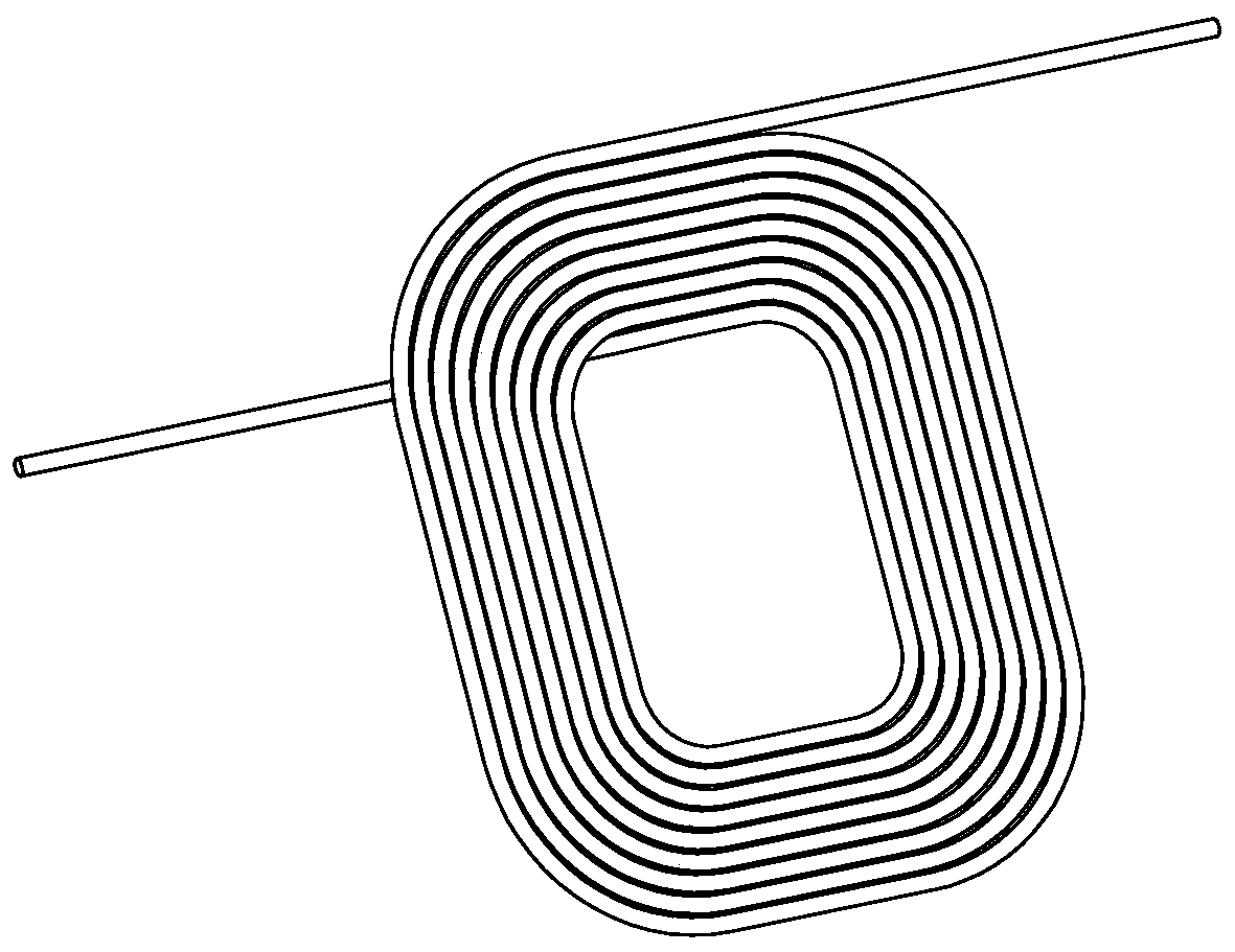
[0040] refer to figure 1 , figure 1 Shown is the coil wound by the existing winding machine;

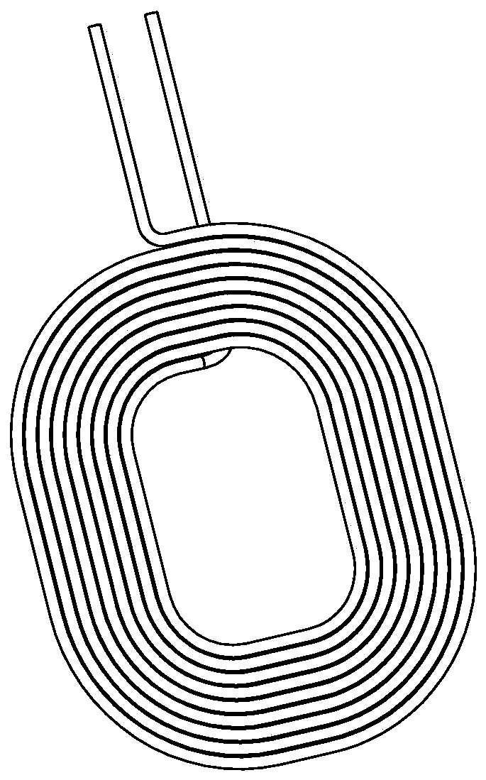
[0041] refer to figure 2 , figure 2 Shown is the coil wound by the coil winding machine provided by the present invention.

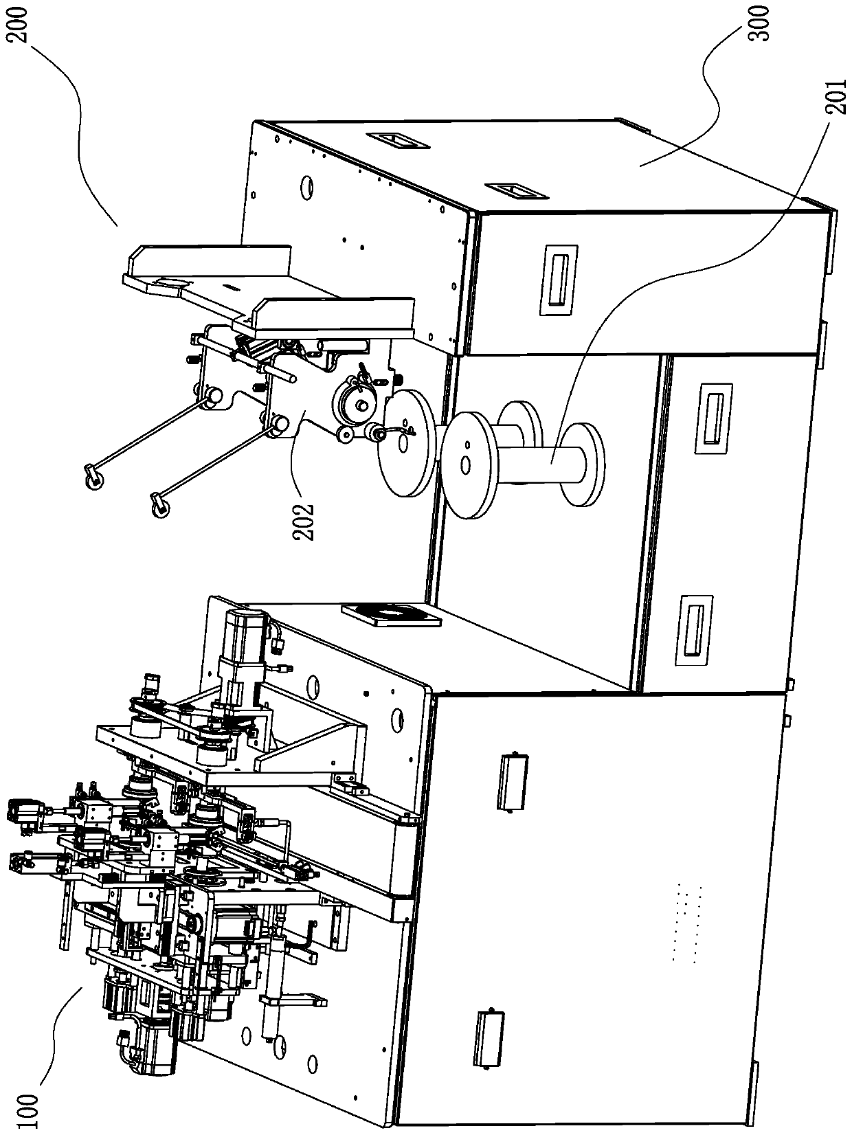
[0042] refer to image 3 , a coil winding machine, which includes a winding machine main body 100, a wire supply mechanism 200 and a machine platform 300, and the winding machine main body 100 and the wire supply mechanism 200 are arranged on the machine platform 300;

[0043] refer to Figure 4 and Figure 5 , the main body 100 of the winding machine includes a frame 1, a winding jig 2, a bending posit...


PUM


Abstract

The invention discloses a coil winding machine. The coil winding machine comprises a winding machine main body; the winding machine main body comprises a machine frame, a winding jig and a bending andpositioning mechanism; the winding jig comprises a front mold and a winding core; the front mold surface of the front mold is provided with a coil containing groove, an outer ring needle hole and aninner ring needle hole; and the bending and positioning mechanism comprises an outer ring bending needle, an inner ring bending needle and a bending needle telescopic driving device. The inner ring bending needle and the coil containing groove are used for positioning the position where pins of inner rings of coils are bent and shaped; the position where pins of outer rings of the coils are bent is positioned by adopting the outer ring bending needle; and the consistency of the formed coils is good. Furthermore, a coil feeding mechanism, a coil grabbing mechanical arm, a jig rotating driving mechanism and a coil shearing mechanical arm are matched to complete coil winding, so that the production efficiency is high, and waste coils cannot be generated. Moreover, a coil stripping mechanism and a coil conveying line are adopted to complete the discharging of the finished coils, so that the automation degree is high.

Description

technical field [0001] The invention relates to manufacturing equipment of electronic components, especially a coil winding machine. Background technique [0002] An existing coil is a hollow ring-shaped flat coil wound from a coil wire, which can be used to manufacture a wireless charger. In existing coil winding machines, the pins of the wound coils can only protrude naturally tangentially, such as figure 1 shown. The follow-up process needs to bend the pins of the coil, and the pins point to the direction from the inner ring to the outer ring, such as figure 2 shown. If manual positioning is adopted, the difference in the operation level of the workers will lead to differences in the positioning of the pin bending position and the difference in the forming effect, and the coil consistency will be poor, which will affect the subsequent process. Contents of the invention [0003] The purpose of the present invention is to solve at least one of the technical problems ...

Claims


Application Information

Patent Timeline
IPC IPC(8): H01F41/06H01F41/074H01F41/076H01F41/096
CPCH01F41/06H01F41/074H01F41/076H01F41/096
Inventor 沈雪平时彦龙臧俊涛李雄何小利李保玉王世丽张剑赵亚冬陈宏斌
Owner ZHONGSHAN SANLE ELECTRONICS CO LTD
Why Eureka
Try Eureka