
Floating type direct extrusion casting mold and implementing method thereof

A technology of squeeze casting and implementation method, which is applied in the field of floating direct squeeze casting molds, can solve problems such as uneven elastic support force, spring stiffness error, difficult and stable movement, etc., to improve the quality of castings and increase extrusion area, good consistency of effect

Inactive Publication Date: 2013-02-13
SOUTH CHINA UNIV OF TECH
View PDF8 Cites 9 Cited by
  • Summary
  • Abstract
  • Description
  • Claims
  • Application Information

AI Technical Summary

Problems solved by technology

These two patents use two or more springs to support the floating structure. Due to the stiffness error of the spring itself, the change of the elastic coefficient at different temperatures, and the unevenness of the elastic support force, the floating structure The guide precision requirements are high, and it is difficult to ensure smooth movement when the casting is large
Another example is that the mold structure with the code D-T4A4DOX1BOL4R0 adopts the form of the lower hydraulic cylinder to support the floating structure, but the demoulding of the structure is more complicated, and the oil circuit design of the lower hydraulic cylinder is more complicated, and it is also difficult during the extrusion process. Guarantee the action coordination between the upper die and the floating structure and the lower hydraulic cylinder
The above mold structures are all based on quantitative pouring, so the quantitative requirements for molten metal are relatively high, otherwise it will have a certain impact on the consistency of the product

Method used


Image

  • Floating type direct extrusion casting mold and implementing method thereof
  • Floating type direct extrusion casting mold and implementing method thereof
  • Floating type direct extrusion casting mold and implementing method thereof

Examples


Embodiment Construction

[0028] The present invention will be further described in detail through the following examples and accompanying drawings, but the embodiments of the present invention are not limited thereto.

[0029] The aluminum alloy wheel hub is manufactured by the invention.

[0030] The casting machine used in this example is a 16000KN vertical casting machine ((model LY-1600)), and the conveying system adopts an electromagnetic pump (model EMPS-LC). You can also choose to use a pneumatic conveying system or Mechanical piston conveying system.

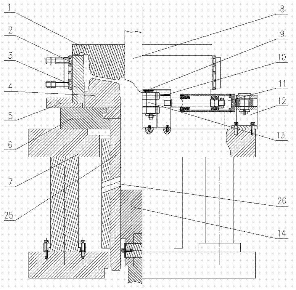
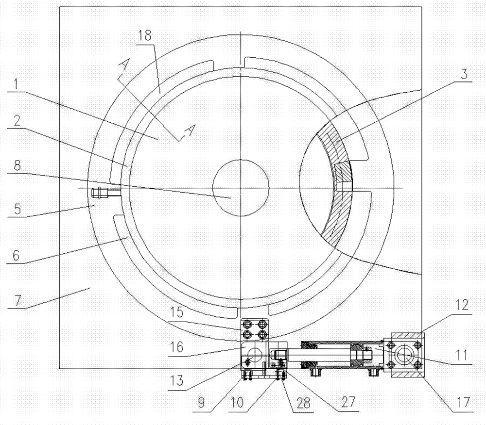
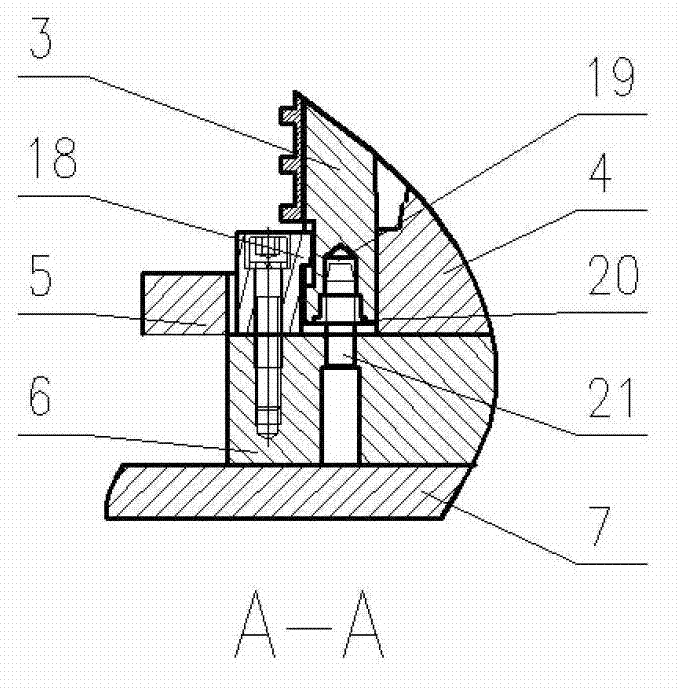
[0031] The floating type direct extrusion casting mold that this embodiment applies manufactures the aluminum alloy wheel hub, as figure 1 , 2 The floating direct extrusion casting mold shown is mainly composed of an upper mold 1, a moving coil heating jacket 2, a moving coil 3, a lower mold 4, a moving coil spacer 5, a lower mold base 6, a mold base 7, and a center cone 8. , its connection relationship with pad hydraulic cylinder 11, hydraul...


PUM


Abstract

The invention discloses a floating type direct extrusion casting mold and an implementing method thereof. A central cone of the mold is embedded in an upper mold; a movable ring is embedded in a lower mold; the movable ring is placed on a movable ring cushion block; the movable ring cushion block is placed on a lower mold base; a movable ring limiting block is fixedly connected to the lower mold base; and a cushion block connecting head is fixedly connected with the movable ring cushion block and matched with a hydraulic cylinder connector by a connector rotating shaft. The upper mold moves downwards, so that an alloy melt is full of a cavity and the alloy melt is extruded; meanwhile, the movable ring and the movable ring cushion block are extruded; the movable ring cushion block rotates under a pressure, so that the movable ring moves downwards along with the upper mold; and excessive alloy melt flows out from an overflow groove. According to the invention, the movable ring is rigidly supported by the movable ring cushion block to rotate along with the movable ring cushion block and the movable ring can stably move downwards, so that the alloy melt uniformly flows out from the overflow groove; therefore, the quality of a cast is guaranteed. The floating type direct extrusion casting mold disclosed by the invention is especially suitable for manufacturing medium and large sized non-ferrous alloy casts by using a plurality of casting methods.

Description

technical field [0001] The invention relates to the field of direct squeeze casting, in particular to a floating direct squeeze casting mold especially suitable for producing medium and large non-ferrous alloy castings and an implementation method thereof. Background technique [0002] The traditional direct squeeze casting process uses the upper die to squeeze the molten metal, the extrusion surface is the outer surface of the upper die, and the lower die only supports the pressure given by the upper die. [0003] The working principle of the direct extrusion casting floating mold structure is that a certain amount of alloy melt is introduced into the cavity, the upper mold is pressed down to contact the alloy melt, and the alloy melt rises under pressure to fill the cavity. When the upper mold is in contact with the floating structure, the pressure of the upper mold is exerted on both the alloy melt and the floating structure, so that the floating structure is driven downw...

Claims


Application Information

Patent Timeline
IPC IPC(8): B22D18/02
Inventor 张文闵好年邵明邱诚张大童
Owner SOUTH CHINA UNIV OF TECH
Learn More