[0021] The technical solutions of the embodiments of the present invention will be clearly and completely described below in conjunction with the accompanying drawings. Obviously, the described embodiments are only a part of the embodiments of the present invention, rather than all the embodiments. Based on the embodiments of the present invention, all other embodiments obtained by those of ordinary skill in the art without creative work are within the protection scope of the present invention. In the description of the present invention, it should be noted that, The terms "center", "upper", "lower", "left", "right", "vertical", "horizontal", "inner", "outer", etc. indicate the orientation or positional relationship based on the drawings The orientation or position relationship is only for the convenience of describing the present invention and simplifying the description, rather than indicating or implying that the device or element referred to must have a specific orientation, be constructed and operated in a specific orientation, and therefore cannot be understood as a limitation of the present invention .
[0022] In addition, the terms "first", "second", and "third" are only used for descriptive purposes, and cannot be understood as indicating or implying relative importance. In the description of the present invention, it should be noted that unless otherwise explicitly stated To stipulate and limit, the terms "installation", "connection" and "connection" should be understood in a broad sense, for example, it can be a fixed connection, a detachable connection, or an integral connection; it can be a mechanical connection or an electrical connection ; It can be directly connected, or indirectly connected through an intermediate medium, and it can be the internal communication between two components. For those of ordinary skill in the art, the specific meaning of the above-mentioned terms in the present invention can be understood in specific situations.
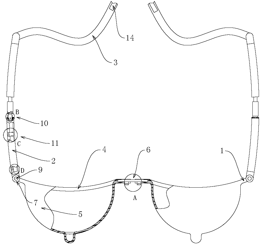
[0023] Such as Figure 1-9 The shown bracket device for post-breast surgery includes two arc-shaped front plates 1 and a side plate 2 composed of two parts, wherein the two front plates 1 are movably connected by a plurality of first telescopic mechanisms 6 , Constitute a structure for adjusting the distance between the two front plates 1, which is convenient to adjust according to the distance between different breast glands, so that the front plate 1 can better cover the front of the body. The front plate 1 is provided with an opening 4, and the front plate 1 at the opening 4 is fixed with a support cover 5 with ventilation holes, which is convenient for the breast to enter the support cover 5 through the opening 4, so as to protect and prevent the wound from cracking. The ventilation holes on the support cover 5 facilitate the ventilation of the wound, so that the healing efficiency can be accelerated. The side panels 2 are hingedly connected to the two sides of the two front panels 1 to facilitate attachment from both sides of the body, so that the front panel 1 is more comfortable and firmly attached to the front of the body. The two parts of the side plate 2 are movably connected by the adjusting mechanism 10 to form a structure that can be adjusted freely. It is convenient to adjust the angle between the two parts of the side plate 2 through the adjusting mechanism 10, so as to adapt to different human bodies, so that the side plate 2 can Fits better to the body. The two ends of the side plate 2 are movably connected with a number of second telescopic mechanisms 11 to form a structure for adjusting the overall length of the side plate 2, which facilitates the adjustment of the length of the side plate 2 through the second telescopic mechanism 11, so as to adapt to different people's body types. , So that the entire device can be more firmly and comfortably attached to the body. The end of the side plate 2 away from the front plate 1 is movably connected with a binding belt 3, and a Velcro 14 is fixed on the binding belt 3, so that the front plate 1 and the side plate 2 can be placed on the body through the binding belt 3 to prevent slippage. The velcro 14 facilitates the adjustment and quick disassembly of the tie belt 3.
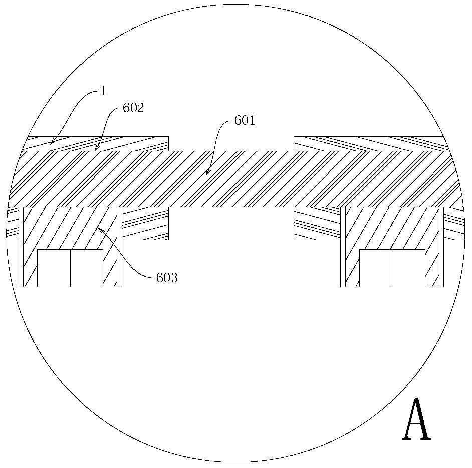
[0024] Such as Figure 1-9 As shown in the bracket device for post-breast surgery, the first telescopic mechanism 6 includes a first telescopic plate 601 and a first adjusting screw 603, and a plurality of first telescopic grooves are opened on the side ends of the two front plates 1 close to each other. 602. The first telescopic plate 601 is slidably connected in the two opposite first telescopic grooves 602, so that the distance between the two front plates 1 can be changed by changing the length of the first telescopic plate 601 out of the first telescopic groove 602, and then The support cover 5 on the front plate 1 can be set on the two breasts, and the fourteenth step and the first telescopic groove 602 are matched with each other to make the connection between the two front plates 1 stronger and form A whole. The side edge of the front plate 1 is provided with a first adjustment screw hole communicating with the first expansion groove 602, and the first adjustment screw hole is close to the outer end of the first expansion groove 602, and the first adjustment screw 603 is threadedly connected to the first expansion groove 602. The adjusting screw hole constitutes a structure for fixing the first telescopic plate 601 in the first telescopic groove 602, which is convenient to control whether the first adjusting screw 603 is aligned by adjusting the length of the first adjusting screw 603 in the first adjusting screw hole. The first telescopic plate 601 is fixed, so as to control the length of the first telescopic plate 601 outside the first telescopic groove 602. The two front plates 1 and the support cover 5 are covered with medical fabrics to avoid direct contact between the front plate 1 and the support cover 5 with human skin, and make the human body feel more comfortable. The cloth is provided with a through hole at the first adjusting screw 603, which facilitates the rotation of the first adjusting screw 603 from the outside, thereby controlling the first telescopic mechanism 6 to expand and contract.
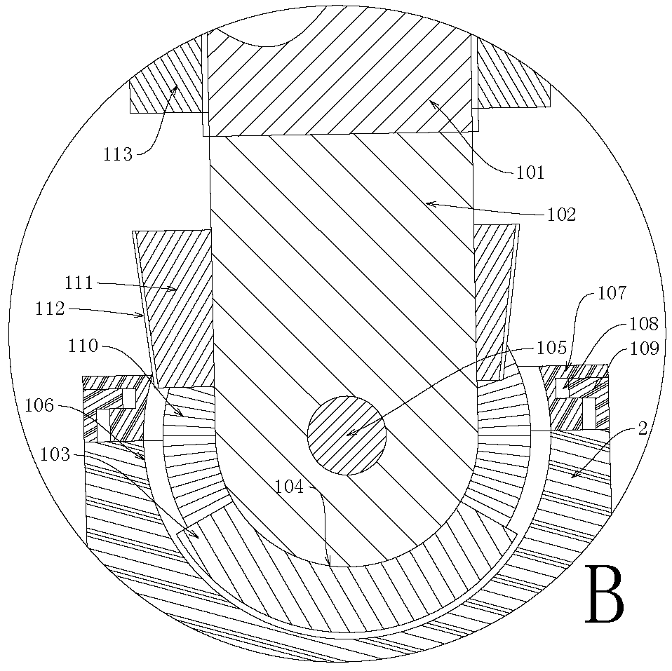
[0025] Such as Figure 1-9 As shown in the bracket device for breast surgery, the adjustment mechanism 10 includes a rotating rod 101, a rotating head 102, a rotating ball 103, a limit ring 107, a block 111 and a sleeve 113, and one end of the rotating rod 101 is welded and fixed On the side end surface of a part of the side plate 2, the rotating rod 101 and a part of the power generation of the side plate 2 form a whole. The rotating head 102 is welded and fixed to the end of the rotating rod 101 away from the side plate 2, and the rotating head 102 is plate-shaped, so that the folding rod can be better connected to the column rotating ball 103 through the rotating head 102. The rotating ball 103 is provided with a rotating groove, and the rotating head 102 is inserted into the rotating groove and is hingedly connected by a pin 105 to form a structure in which the rotating head 102 rotates at a certain angle with the pin 105 as the axis of rotation in the rotating groove, which is convenient for rotating The head 102 rotatably connects the rotating rod 101 with the rotating ball 103, and makes the rotating rod 101 a small pot as the rotating shaft and can only rotate at a certain angle in the rotating groove. The side end surface of the other part of the side plate 2 is provided with a storage slot 106, and the rotating ball 103 is rotatably connected in the storage slot 106 to facilitate the rotation of the rotating ball 103 in the storage slot 106, thereby adjusting the angle between the two parts of the side plate 2. . The limit ring 107 is sleeved on the outer side of the rotating ball 103, so that the rotating ball 103 can be limited by the limit ring 107, so that the rotating ball 103 can only be in the storage groove 106 and prevents the rotating ball 103 from falling out of the storage groove 106. The outer surface of the limit ring 107 is provided with a limit groove 108, the side end surface of the side plate 2 at the storage groove 106 is welded and fixed with an L-shaped limit plate 109, and one end of the limit plate 109 is slidably connected to the limit groove In 108, a limit ring 107 is formed to be slidably connected to a part of the side end surface of the side plate 2, so that the limit ring 107 is limited on the side plate 2 by the limit plate 109, and does not affect the rotation of the limit ring 107. The clamping block 111 is eccentrically sleeved on the rotating head 102, and the width of the end of the clamping block 111 close to the rotating ball 103 is smaller than the width of the end far away from the rotating ball 103, so that the vertical section of the clamping block 111 is an isosceles trapezoid and runs along the rotating groove. The width of the opening 4 on both sides of the rotating head 102 in the direction of the opening 4 is different, so that when the block 111 is inserted into the rotating slot 104, the limit ring 107 can be moved to one side through the inclined and eccentric setting, thereby making the limit The empty storage slot 106 in the middle of the ring 107 is misaligned, so that the rotating ball 103 can be fixed, so that the rotating ball 103 cannot rotate in the storage slot 106. The rotating groove 104 has a conical arc surface centered on the pin 105, and is provided with an outer tooth groove 110. The outer surface of the block 111 is provided with an inner tooth groove 112. The outer tooth groove 110 and the inner tooth groove 112 are meshed with each other to facilitate When the blocking block 111 moves into the rotating groove 104, the external tooth groove 110 and the external tooth groove 110 are engaged so that the blocking block 111 can only slide up and down, so that the rotating head 102 and the rotating rod 101 cannot rotate. The sleeve 113 is threadedly connected to the rotating rod 101 to form a structure for adjusting the depth of the clamping block 111 inserted into the rotating groove 104, which is convenient to retreat to you. The rotating sleeve 113 makes the sleeve 113 slide up and down on the rotating rod 101, thereby making the sleeve 113 presses the clamping block 111 into the rotating groove 104 to realize the function of fixing the bayonet.
[0026] Such as Figure 1-9 As shown in the bracket device for post-breast surgery, the second telescopic mechanism 11 includes a second telescopic plate 1101, a slider 1105, a second adjusting screw 1107, and a stop block 1108. The side plates 2 are provided on both end surfaces There are several second telescopic grooves 1102, and the second telescopic plate 1101 is slidably connected in the second telescopic groove 1102, so that the length of the entire side plate 2 can be changed by adjusting the length of the second telescopic plate 1101 in the second telescopic groove 1102, thereby facilitating side The board 2 can be suitable for people of different body types. The outer end surface of the side plate 2 is provided with a communicating groove 1103 that communicates with the second telescopic groove 1102. The two end surfaces of the communicating groove 1103 are provided with guide bars 1104. The sliding grooves 1106 are provided on both end surfaces of the slider 1105, and the slider 1105 The guide bar 1104 and the sliding groove 1106 are slidably connected in the communicating groove 1103, the slider 1105 and the second telescopic plate 1101 are still provided with a communicating second adjusting screw hole, and the second adjusting screw 1107 passes through the second adjusting screw hole. It is screwed on the slider 1105 and the second telescopic plate 1101, so that the slider 1105 and the second telescopic plate 1101 can be connected together by the second adjusting screw 1107 to form a whole, and it can also make the slider 1105 and the second telescopic plate 1101. The plate 1101 slides bitterly in the communicating groove 1103 and the second sliding groove. In addition, the second adjusting screw 1107 can be used to fix the sliding block 1105 and the second telescopic plate 1101 in the second telescopic groove 1102 to control the second telescopic groove. The plate 1101 deepens the length outside the second telescopic groove 1102, thereby adjusting the overall length of the side plate 2. The limit block 1108 is welded and fixedly connected to the end of the opening 4 of the communicating groove 1103, which is convenient for closing the opening 4 of the communicating groove 1103 after the sliding block 1105 is slidably connected in the communicating groove 1103 to prevent the sliding block 1105 from falling out of the communicating groove 1103 , Thereby preventing the second telescopic plate 1101 from falling out of the second telescopic groove 1102.
[0027] Such as Figure 1-9 In the bracket device used for post-breast surgery, the first connector 7 is welded and fixedly connected to the side end surface of the front plate 1, and the second telescopic plate 1101 is welded and fixedly connected to the end of the side plate 2 with a connecting block. 12. A second connector 8 is fixedly connected to the connecting block 12 by welding. The first connector 7 and the second connector 8 are hingedly connected by a hinge rod 9 to form a hinged connection structure of the front plate 1 and the side plate 2, which is convenient to pass through A connecting head 7, a second connecting head 8 and a hinge rod 9 hinge the front panel 1 and the side panel 2 together to form a whole, so that the front panel 1 and the side panel 2 can be firmly and comfortably attached to the body. The second connecting head 8 far away from the front plate 1 is provided with a connecting hole 13, one end of the binding belt 3 passes through the connecting hole 13 and is fixed on the side plate 2 by needles and threads, and a Velcro 14 is fixed on the restraining belt 3 away from the side plate 2. One end of the strap, so that the strap 3 can fix the entire device on the body. The side plate 2 is wrapped with medical cloth to avoid direct contact between the side plate 2 and the body, and at the same time, it can increase the comfort of contact between the device and the body, and avoid the connection between the side plate 2 and the connection between the side plate 2 and the front plate 1. Physical injury. The medical cloth is provided with through holes at the communicating groove 1103 and the adjusting mechanism 10 to facilitate the operation of the second adjusting screw 1107 and the adjusting mechanism 10 to adjust the entire device.
[0028] The above-mentioned embodiments only express several embodiments of the present invention, and the descriptions are more specific and detailed, but they should not be understood as limiting the scope of the invention patent. It should be pointed out that for those of ordinary skill in the art, without departing from the concept of the present invention, several modifications and improvements can be made, and these all fall within the protection scope of the present invention. Therefore, the protection scope of the patent of the present invention should be subject to the appended claims.