Pulling wire fixing device of bendable sheathing canal
A technology of fixing devices and wires, applied in the direction of catheters, etc., can solve the problems of increased diameter of the distal end of the adjustable curved sheath, concentration of welding stress at the connection point, and low connection strength, so as to reduce the surgical wound, ensure reliable fixed connection, The effect of improving product safety
- Summary
- Abstract
- Description
- Claims
- Application Information
AI Technical Summary
Problems solved by technology
Method used
Image

Examples
Embodiment 1
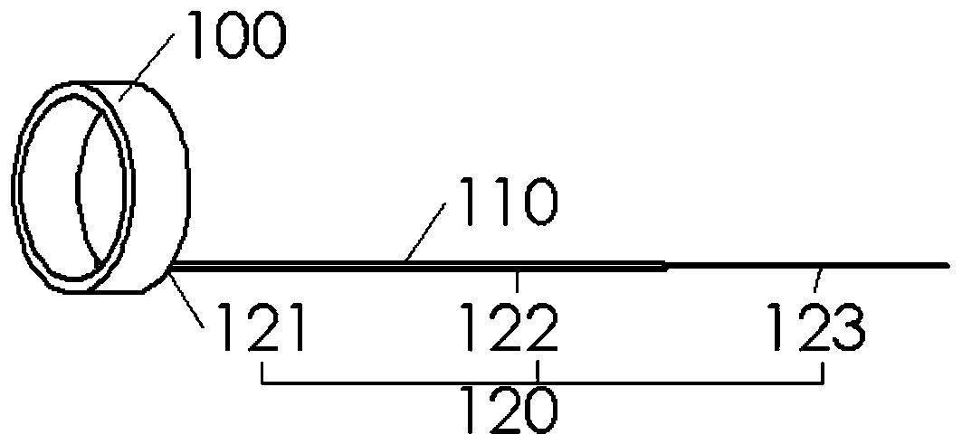
[0033] The invention is mainly applied in the field of bending-adjusting sheaths, and relates to a novel pull-wire fixing device for adjustable bending sheaths. Such as figure 1 As shown, the pull wire fixing device includes a pull ring 100 and a pull wire 120, the pull ring 100 is arranged at the distal end of the adjustable bend sheath, and is fixedly connected with the adjustable bend sheath, in the pull ring The tube wall of 100 is provided with a pull wire receiving groove, the distal end 121 of the pull wire 120 is placed and fixed in the pull wire receiving groove, and the proximal end 123 of the pull wire 120 extends out of the body. The main body portion 122 of the pull wire 120 is placed within the pull wire channel 110 .
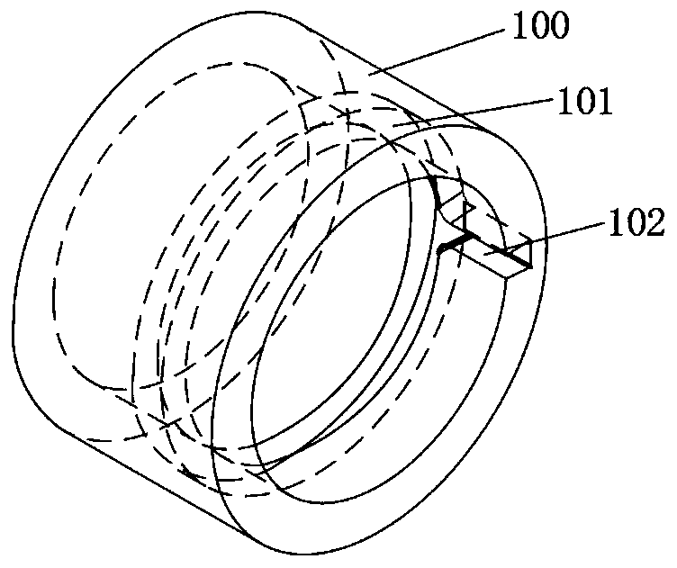
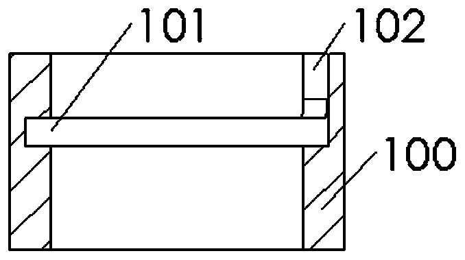
[0034] Such as figure 2 with image 3 As shown, the pull wire receiving groove is divided into two parts, the first part is a straight groove 102 arranged longitudinally along the inner wall of the pull ring 100, which can only accommodate two...
Embodiment 2
[0038] Such as figure 1 , Figure 4 with Figure 5 As shown, the difference between this embodiment and the first embodiment is that the stay wire receiving groove is divided into two parts, and the first part is a straight groove 102 arranged longitudinally along the outer wall of the pull ring 100, which can only accommodate side-by-side There are two pull wires 120 , the second part is an annular groove 101 arranged along the circumferential direction of the outer wall of the pull ring 100 , which can only accommodate one pull wire 120 . The distal end 121 of the pull wire 120 enters from the straight groove 102, and ends at the straight groove 102 after going around the annular groove 101, and the proximal end 123 of the pull wire 120 extends out Outside the body, the main body 122 of the pull wire 120 is placed in the pull wire channel 110, and the pull wire channel 110 is in a cylindrical structure, and its inner diameter is slightly larger than the outer diameter of t...
Embodiment 3
[0040] Such as Image 6 with Figure 7 As shown, the difference between this embodiment and the first embodiment is that the pull ring 100 is composed of a ring pull seat 104 and a ring pull cover 105, and an annular protrusion 106 and a rectangular protrusion 107 are arranged on the ring pull cover 105 , an annular groove 101 matching the shape of the annular protrusion 106 and a straight groove 102 matching the shape of the rectangular protrusion 107 are arranged on the ring holder 104, the ring The cover 105 fixes the distal end 121 of the pull wire 120 in the annular groove 101 and the straight groove 102 provided on the pull ring seat 104 through the annular protrusion 106 and the rectangular protrusion 107 . That is, after the distal end 121 of the pull wire 120 enters along the straight groove 102, it circles around the inner wall of the annular groove 101 and places it at the inner wall of the straight groove 102, and the pull ring cover 105 is covered, and the pull w...
PUM
 Abstract
Description
Claims
Application Information
 - R&D
- Intellectual Property
- Life Sciences
- Materials
- Tech Scout
- Unparalleled Data Quality
- Higher Quality Content
- 60% Fewer Hallucinations
Browse by: Latest US Patents, China's latest patents, Technical Efficacy Thesaurus, Application Domain, Technology Topic, Popular Technical Reports.
© 2025 PatSnap. All rights reserved.Legal|Privacy policy|Modern Slavery Act Transparency Statement|Sitemap|About US| Contact US: help@patsnap.com