Railway vehicle axle temperature monitoring method and system

A technology for railway vehicles and monitoring systems, applied in railway vehicle shape measuring instruments, railway car body components, railway auxiliary equipment, etc., can solve the problems of transmission, short time, and long time.

Active Publication Date: 2019-09-10
CHINA SHENHUA ENERGY CO LTD +2
View PDF4 Cites 0 Cited by
  • Summary
  • Abstract
  • Description
  • Claims
  • Application Information

AI Technical Summary

Problems solved by technology

[0004] The existing temperature measurement method is to start the temperature measurement after receiving the measurement instruction after identifying the electronic tag through the multi-tag anti-collision process. This process takes a long time. When the railway vehicle is running at high speed, the tag is read The time in the electromagnetic field area of ​​the writer is extremely short, and more than one electronic tag enters the electromagnetic field at the same time. The above process may cause the problem that the electronic tag fails to transmit the measured data and its own data to the electronic tag reader after passing through the electromagnetic field.

Method used


Image

  • Railway vehicle axle temperature monitoring method and system
  • Railway vehicle axle temperature monitoring method and system
  • Railway vehicle axle temperature monitoring method and system

Examples


Embodiment 1

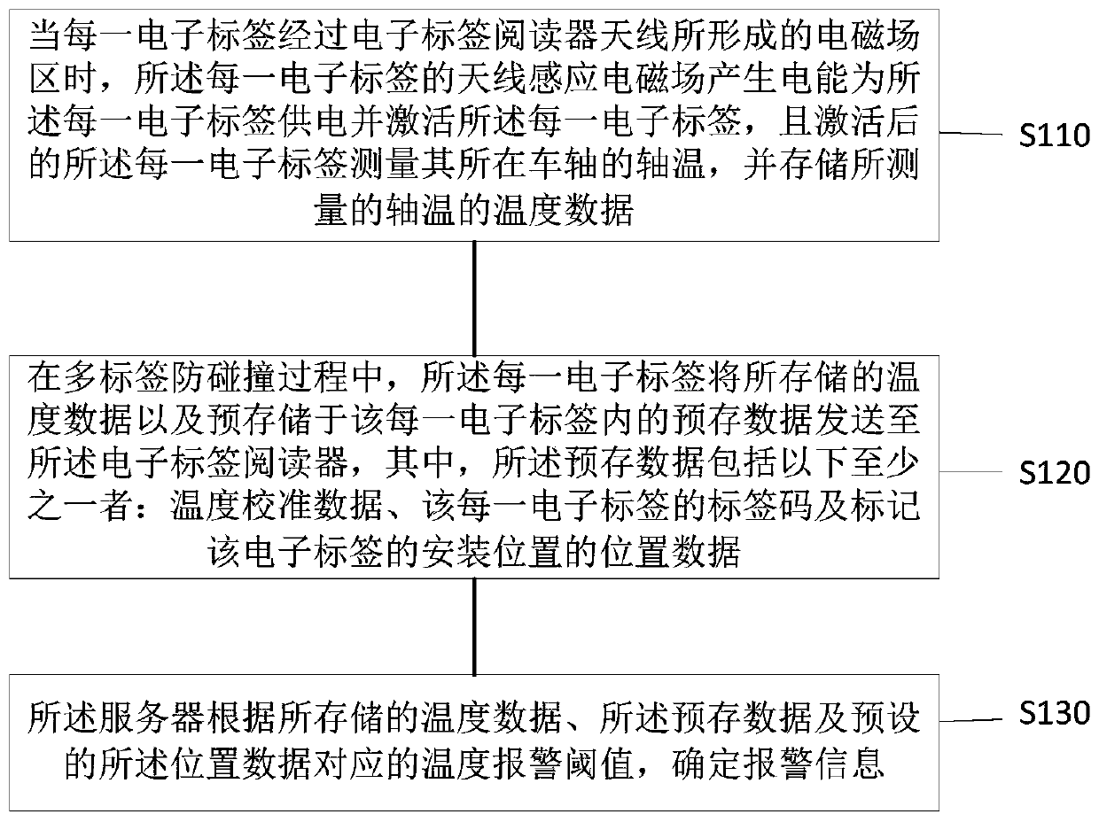
[0036] figure 1 It is a flow chart of the specific method of Embodiment 1. In the first embodiment, electronic tags capable of measuring axle temperature are arranged on the axles of each railway vehicle, and each electronic tag is configured to obtain electric energy in the magnetic field of a suitable electronic tag reader antenna installed on the ground.

[0037] Such as figure 1 As shown, the axle temperature monitoring method may include:

[0038] S110, when each electronic tag passes through the electromagnetic field area formed by the antenna of the electronic tag reader, the antenna of each electronic tag induces an electromagnetic field to generate electric energy to supply power to each electronic tag and activate each electronic tag, and Each activated electronic tag measures the axle temperature of the axle where it is located, and stores the temperature data of the measured axle temperature.

[0039] Wherein, the antenna of each electronic tag induces an electr...

Embodiment 2

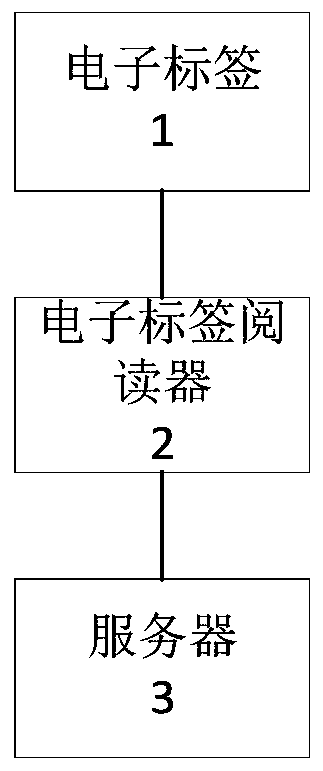
[0055] figure 2 It is a module connection block diagram of an axle temperature monitoring system of a railway vehicle.

[0056] Such as figure 2 As shown, the second embodiment provides an axle temperature monitoring system of a railway vehicle. The axle temperature monitoring system includes: each electronic tag 1 is arranged on the axle of each railway vehicle, and is used to measure the axle temperature and store the measured temperature. The temperature data of the shaft temperature and the pre-stored data are used to obtain electric energy in the electromagnetic field of the compatible electronic tag reader 2 antenna, wherein each electronic tag 1 is also used for when it passes through the electronic tag reader 2 antenna When the electromagnetic field is formed, the antenna induction electromagnetic field of each electronic tag 1 generates electric energy to power each electronic tag 1 and activate each electronic tag 1, and each electronic tag 1 after activation Mea...

Embodiment 3

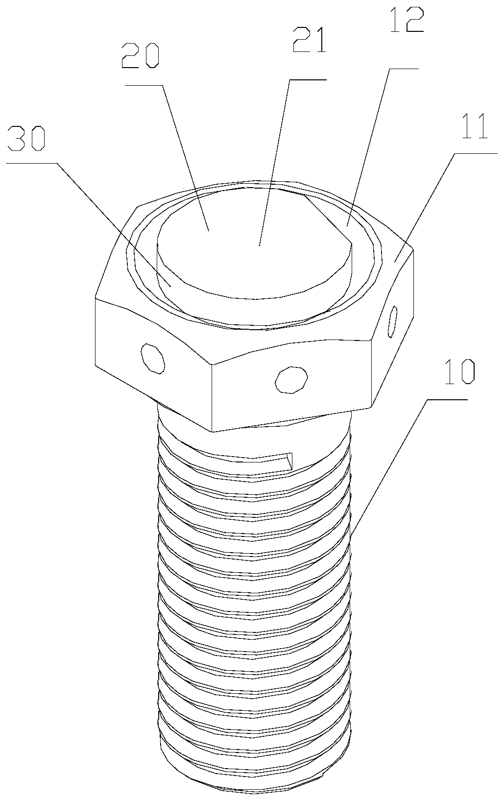
[0062] Before describing the third embodiment in detail, the structure of the existing electronic tag will be briefly introduced. In the existing electronic tags, a structure in which a rigid antenna, a bolt and a temperature sensing module cooperate is adopted, and the whole temperature sensing module and the rigid antenna are mainly designed inside the bolt. Due to the nature of the rigid antenna itself (large volume, not easy to fix), it can only be designed inside the bolt, and the design inside the bolt will affect the efficiency of data transmission, which will not affect the original slow-speed railway vehicles. However, when used on high-speed railway vehicles at the present stage, the transmission efficiency of the existing electronic tags cannot meet the requirements, and in severe cases, the temperature data cannot be transmitted.

[0063] image 3 is a schematic diagram of the structure of the electronic tag; Figure 4 is a schematic diagram of the structure of t...


PUM


Abstract

The embodiment of the invention provides an axle temperature monitoring method and system for a railway vehicle, and relates to the field of axle temperature measurement; the axle temperature monitoring method comprises the following steps: each electronic tag measures and stores the axle temperature of the railway vehicle where each electronic tag is located based on an electric energy acquisition condition and a corresponding electric energy acquisition time of each electronic tag, wherein each electronic tag also stores pre-stored data comprising a tag TID / EPC code, temperature calibrationdata, and data related to an axle number, a bearing position number, an axle model, a bearing model and the like where a tag installation position is located; an electronic tag reader obtains the axletemperature and pre-stored data of the railway vehicle where each electronic tag is located, wherein the axle temperature and pre-stored data are stored in each electronic tag; and alarm informationis determined based on the axle temperature of the railway vehicle acquired by the electronic tag reader, the pre-stored data and a preset temperature alarm threshold value of the bearing position number. According to the method and system, the temperature measurement time can be reduced, and the temperature can be accurately monitored.

Description

technical field [0001] The invention relates to the field of axle temperature measurement, in particular to an axle temperature monitoring method and system for railway vehicles. Background technique [0002] When the railway vehicle is running fast, due to bearing failure and abnormal high temperature of the bearing, it will cause the hot shaft of the vehicle or the hot shaft accident. At present, the infrared shaft temperature detection system is widely used in freight trains. However, due to the special environment of train operation, the existing infrared shaft temperature detection system is often affected by bad weather, which greatly affects the reliability of shaft temperature measurement, and the operation and maintenance costs are high. [0003] In recent years, with the rapid development of RFID technology, the shaft temperature monitoring method based on passive RFID technology has been gradually applied. The shaft temperature monitoring method of passive RFID ...

Claims


Application Information

Patent Timeline
Patent Type & Authority Applications(China)
IPC IPC(8): B61K9/06G06K17/00
CPCB61K9/06G06K17/0029
Inventor 贾刚李开颜丁春嵘康凤伟李权福王洪昆王文刚边志宏卢宇星王蒙方琪琦王萌刘洋成世毅傅霖煌孔令荣赖远桥
Owner CHINA SHENHUA ENERGY CO LTD
Why Eureka
Try Eureka