Detachable leg structure and glasses including structure

A technology for temples and glasses, applied in the field of glasses, can solve the problems of inconvenient disassembly, inconvenient separation and assembly of temple mounting structures, etc.

Pending Publication Date: 2019-09-10
郭靖宇
View PDF0 Cites 1 Cited by
  • Summary
  • Abstract
  • Description
  • Claims
  • Application Information

AI Technical Summary

Problems solved by technology

[0002] Spectacles that move the temples through hinge joints are already known to us. The spectacle frames are rigid enough to be placed on the face, and the temples, as an important part of the glasses, are inconvenient to disassemble from the spectacle frame. , it is usually nece

Method used


Image

  • Detachable leg structure and glasses including structure
  • Detachable leg structure and glasses including structure
  • Detachable leg structure and glasses including structure

Examples


Embodiment 1

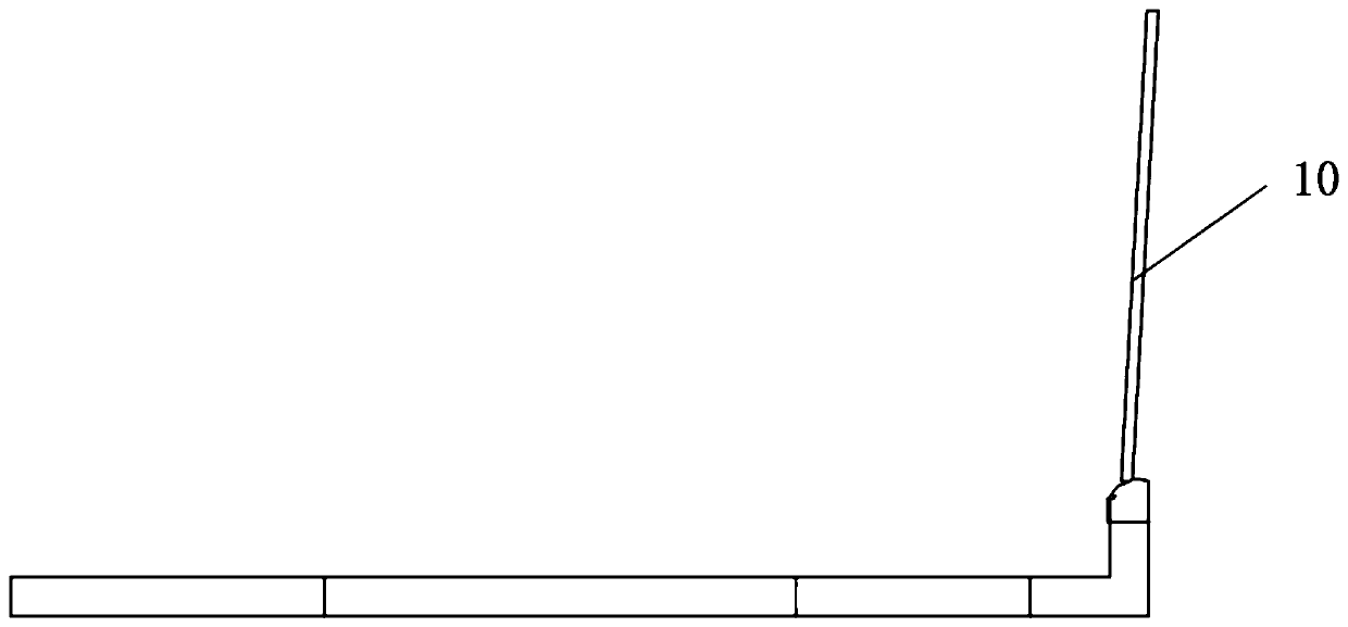
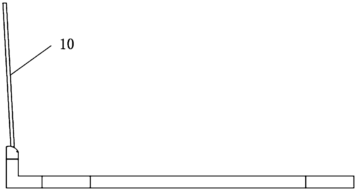
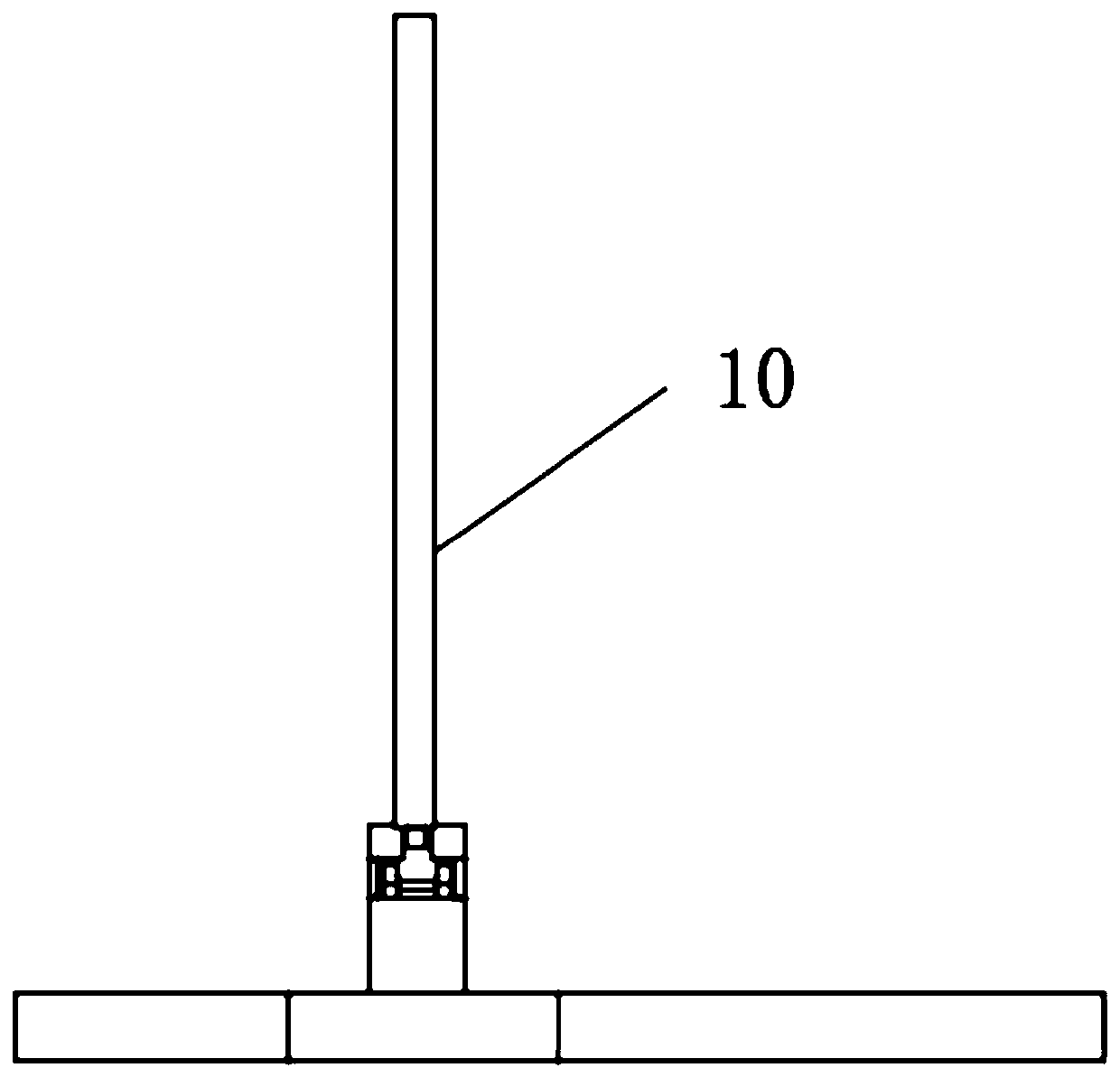
[0046] Embodiment 1: see Figure 1-28As shown, a detachable mirror leg structure includes a mirror leg 10, which also includes a temple root receiving portion 20 and a mirror leg root limiting portion 30 that are rotatably mounted on the connecting portion of the glasses temple. The rimless glasses are taken as an example for illustration, and the same is true for the rimless glasses (the studs of the rimless glasses are equivalent to the connecting parts of the temples mentioned in the rimless glasses), so the description will not be repeated here. Here, the connecting part T of the mirror leg of the glasses is an L-shaped corner structure, and the installation position of the glasses receiving part of the connecting part T of the temples of the glasses is a platform structure 40, and the platform structure is a free end surface of the corner part of the L-shaped corner structure, and the platform The structure is provided with a rotating shaft 401 on which the temple root re...

Embodiment 2

[0054] Embodiment 2: The present invention also provides a pair of glasses, which include the detachable temple structure given in Embodiment 1. Such glasses can conveniently and quickly complete the disassembly and assembly of the temples. The types of glasses include but are not limited to sunglasses, myopia glasses, and radiation-proof glasses.

[0055] exist Figure 12 Among them, the glasses in this figure only show the single-side lens G of the glasses, and the glasses are rimless glasses, and the bridge of the nose between the lens G and the other side lens and the lenses has been omitted, but it does not affect the description of the present invention .

[0056] from Figure 12 It can be seen that the temples are in the unfolded state. At this time, the temples cannot be released from the base of the temples and the supporting structure. At this time, the glasses can be worn on the human body. The glasses with detachable temples can be After the mirror legs are fold...


PUM


Abstract

The invention provides a detachable leg structure and a pair of glasses including the structure, and the detachable leg structure comprises legs, leg root containing portions rotatably mounted at theglasses leg connection portions, and leg root limit portions, wherein the legs are provided with fixing heads; the leg root containing portions are each formed with a containing cavity for containingeach of the leg fixing heads; the leg root limit portions are mounted at the mounting positions of the leg root containing portions at the glasses leg connection portions, the leg root containing portions are built in the leg root limit portions, the leg root limit portions are each provided with an insertion and take-off opening toward the folding direction of the legs and a leg fixing head blocking portion disposed at the upper portion of each of the leg root limit portions, the leg fixing head blocking portions are provided with unfolding and retracting notches for moving the legs from thefolding direction toward the unfolding direction, and the unfolding and retracting notches communicate with the insertion and take-off openings. This kind of glasses can quickly and easily complete the disassembly and assembly work of the legs.

Description

technical field [0001] The invention relates to the technical field of spectacles, in particular to a detachable temple structure and spectacles with the structure. Background technique [0002] Spectacles that move the temples through hinge joints are already known to us. The spectacle frames are rigid enough to be placed on the face, and the temples, as an important part of the glasses, are inconvenient to disassemble from the spectacle frame. , it is usually necessary to use related tools to separate the temples from the spectacle frame. At the same time, it is also necessary to use external tools to install the temples to the spectacle frame. The separation and assembly of the traditional temple mounting structure is quite inconvenient. of. Contents of the invention [0003] The object of the present invention is to provide a detachable temple structure and glasses with the structure, which can conveniently disassemble and assemble the temples and the connecting parts...

Claims


Application Information

Patent Timeline
IPC IPC(8): G02C5/14G02C5/20
CPCG02C5/14G02C5/20
Inventor 郭靖宇
Owner 郭靖宇
Why Eureka
Try Eureka