Double-position adjustable self-keeping fast floating ball valve

A self-holding, floating ball valve technology, applied in the direction of valve details, valve devices, functional valve types, etc., can solve problems such as high cost, waste of energy, difficult water level adjustment, etc.

Pending Publication Date: 2019-09-13
唐山市同智科技有限公司
View PDF1 Cites 4 Cited by
  • Summary
  • Abstract
  • Description
  • Claims
  • Application Information

AI Technical Summary

Problems solved by technology

[0003] In the existing float valve technology, no matter whether the pilot valve is used or not, it is common to use a single float and one liquid level control point. They are all near the installation position of the lever type float valve, and the water inlet water level and the stop water inlet water level are very close, resulting in frequent start and stop of the remote control float ball valve; frequent start and stop of the valve will not only accelerate the impact and wear of the valve sealing surface and easily damage it, but also cause water supply problems. The pressure of the pipe network fluctuates violently, causing damage to the water supply pipe network; there are also occasions where well water is used to supply water to remote pools, in order to maintain the liquid level of the pool, the water supply equipment in front of the float valve needs to run for a long time, which wastes energy and causes accelerated wear of the equipment; For example, electric water boilers that use float valves to control water intake are widely used. After the water is boiled, the water is connected to the back, even if only half a cup of water is connected, the raw water will be added again, etc. Many places really need a device

Method used


Image

  • Double-position adjustable self-keeping fast floating ball valve
  • Double-position adjustable self-keeping fast floating ball valve
  • Double-position adjustable self-keeping fast floating ball valve

Examples


Embodiment 1

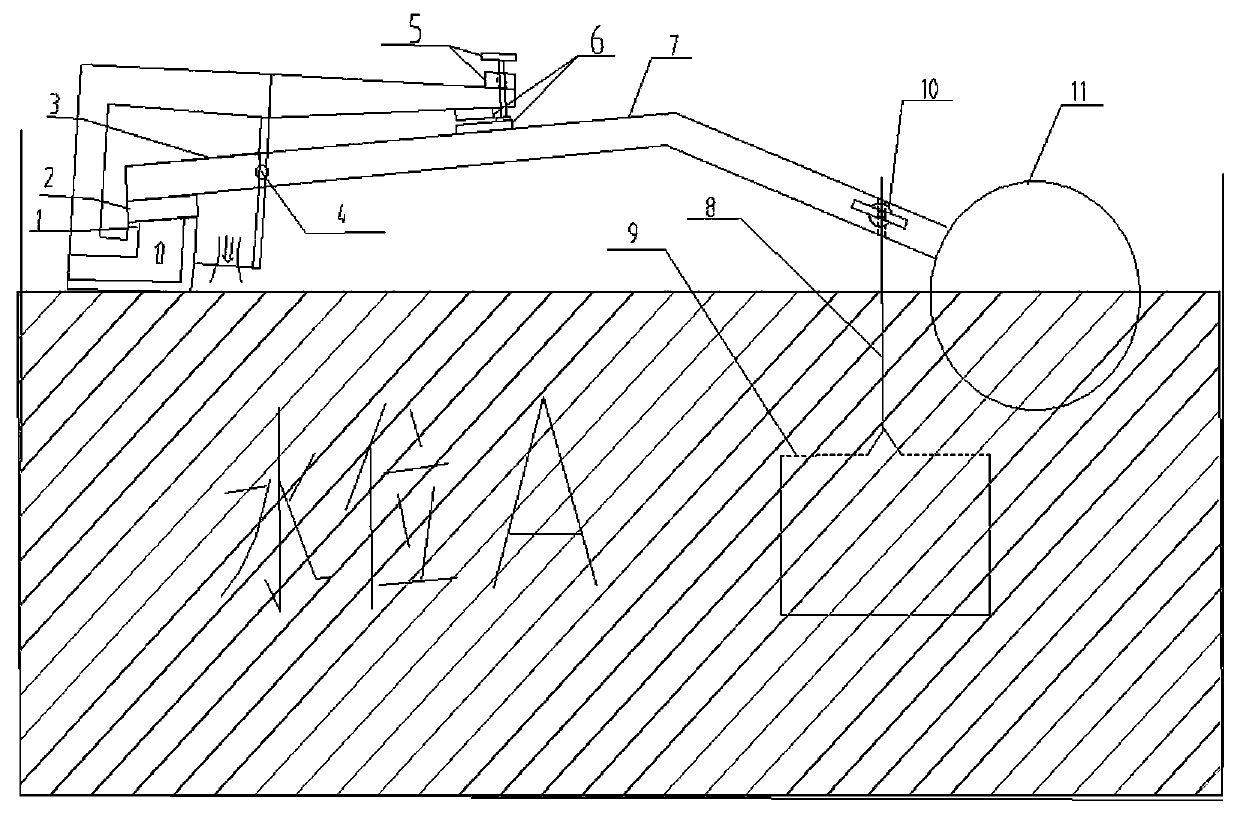
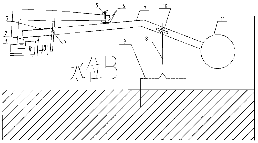
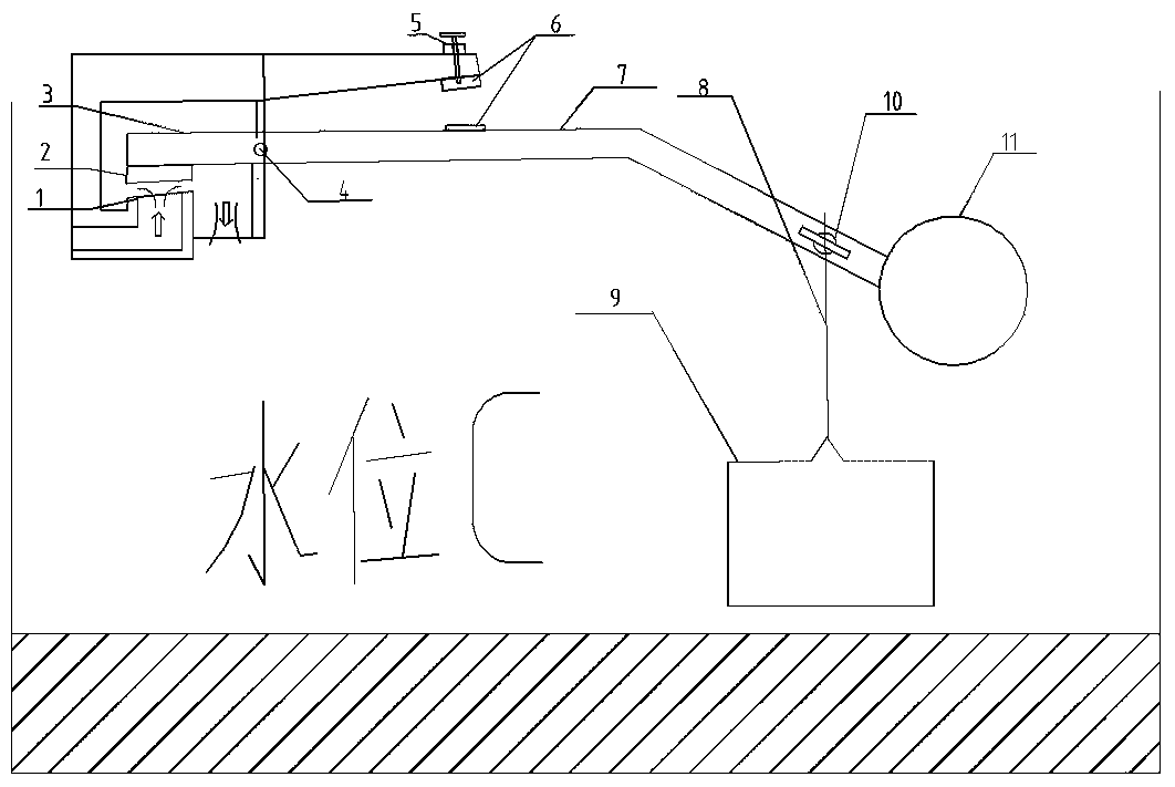
[0029] see figure 1 , one A two-position adjustable self-holding fast float valve, including a valve body, a movable spool 2, the valve body is provided with a valve seat 1 for contacting the movable spool 2, and also includes a short lever arm 3 of the spool, and a valve stem supporting shaft 4. Float lever 7, upper and lower limit adjustment float rod 8, lower limit float 9, upper limit float 11, the movable spool 2 is arranged on one end of the short lever arm 3 of the spool, and the other end of the short lever arm 3 of the spool is connected to the float One end of the lever 7 is connected, the valve stem support shaft 4 is set on the valve body, the connecting part of the valve core short lever arm 3 and the float lever 7 is set on the valve stem support shaft 4, and the upper limit float 11 is set on the float lever 7 The other end of the upper and lower limit adjustment float lever 8 is fixed on the float lever 7, the lower end of the upper and lower limit adjustment...

Embodiment 2

[0042] see Figure 4 , the DN80 remote control float valve is used to match the double-position adjustable self-holding fast float valve of the present invention, specifically for the control of water supply for a 4x3x2m water tank. Pipe to the double-position adjustable self-holding fast float valve of the present invention.

[0043] The diameter of the float valve inlet valve seat 1 is 10mm (the maximum pressure force generated on the movable valve core is 12.56kgf when the maximum pressure is 1.6mpa), and the movable valve core 2 larger than the valve seat 1 is installed on it, and the movable valve seat 2 is connected to the One end of the short lever arm 3 of the spool, the other end of the short lever arm 3 of the spool is connected with the floating ball lever 7 and fixed on the valve stem support shaft 4 at the connected part, in order to minimize the influence of the pipeline pressure change on the switch spool , the length of the float lever 7 is about 8 times of th...


PUM


Abstract

The invention relates to a double-position adjustable self-keeping fast floating ball valve. A valve base, a movable valve element, a valve element lever arm, a valve rod supporting rotating shaft, afloating ball lever, a magnetic force self-keeping mechanism, an upper limit floating ball, a lower limit floating barrel and an upper and lower limit adjusting floating barrel pull rod are included;when the water level is lowered to be lower than the lower limit floating barrel, liquid in the lower limit floating barrel changed into gravity, so that the total gravity borne on a lever is larger than the magnetic keeping attracting force, and the movable valve element connected to the lever is driven to perform fast valve opening; before the liquid level ascends to that the upper limit floating ball is submerged, the total gravity is still larger than buoyancy, and the valve open state is maintained; when the liquid level ascends to that the upper limit floating ball generates a rated buoyancy, the floating ball lever is driven to ascend, and ascends till a magnetic keeping mechanism generates an attracting force, the valve closing force is doubled, and the valve closing process is accelerated so that a water inflow valve can be fast closed; and in the valve closed state, before the liquid level descends to that the lower limit floating barrel is exposed, the valve closed state iskept due to the magnetic attracting force, and therefore double-position adjustable self-keeping fast valve opening and closing of the floating ball valve can be achieved, and the problems of shocking, quivering, abrasion and the like are avoided.

Description

technical field [0001] The invention relates to the technical field of valves, in particular to a two-position adjustable self-holding fast float valve. Background technique [0002] Float valve is a widely used liquid control valve, installed in liquid for automatic control of liquid level. Its main advantage is that it can realize the automatic control of the liquid level without relying on additional energy, and has a series of advantages of simplicity, convenience, and low cost; the principle of the float valve is that the hollow float in the container is made The buoyancy of the floating ball changes, causing the lever connected to the floating ball to move up and down to drive the valve spool connected to it; the buoyancy of the floating ball when the liquid level rises is greater than the medium pressure on the spool of the controlled valve and the total gravity of the floating ball system. is closed; when the liquid level drops, the buoyancy of the float decreases, ...

Claims


Application Information

Patent Timeline
IPC IPC(8): F16K21/18F16K31/08F16K31/28
CPCF16K21/185F16K31/084F16K31/28
Inventor 王连霞刘印同杨越刘胡生侯广军
Owner 唐山市同智科技有限公司
Why Eureka
Try Eureka