Eureka AIR delivers breakthrough ideas for toughest innovation challenges, trusted by R&D personnel around the world.

Femoral far-end osteotomy guide device for knee joint replacement

A technology of knee joint replacement and guiding device, which is applied in the direction of surgical saws, etc., can solve the problems of different femoral structures and sizes, limit the application range of osteotomy surgery, and the inability of osteotomy guide device to adapt, and achieve the effect of expanding the application range of surgery

Pending Publication Date: 2019-09-17
XIANGYA HOSPITAL CENT SOUTH UNIV
View PDF0 Cites 2 Cited by
  • Summary
  • Abstract
  • Description
  • Claims
  • Application Information

AI Technical Summary

Problems solved by technology

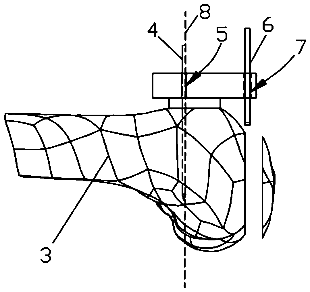
[0003] First, because the guide hole of the existing osteotomy guide device is set at a fixed angle (usually perpendicular to the main plane of the guide device), the pendulum saw can only perform fixed-angle osteotomy through the guide hole 7, but the femur of different patients The structure and size are not the same, and a certain inclination angle needs to be adjusted during the osteotomy process, so the current osteotomy guide device cannot adapt;
[0004] Second, the distance between the two positioning pin socket holes 5 of the osteotomy guide is not only fixed, but also the distances between the two positioning pin socket holes 5 of the osteotomy guides of different manufacturers are not the same, often cannot Fit into two positioning pins 4
[0005] Third, the distance between the two positioning pin socket holes 5 and the guide hole 7 is fixed and cannot be adjusted continuously and accurately during the operation, which greatly limits the application range of the osteotomy operation

Method used


Image

  • Femoral far-end osteotomy guide device for knee joint replacement
  • Femoral far-end osteotomy guide device for knee joint replacement
  • Femoral far-end osteotomy guide device for knee joint replacement

Examples


Embodiment Construction

[0028] The embodiments of the present invention will be described in detail below with reference to the accompanying drawings, but the present invention can be implemented in many different ways defined and covered by the claims.

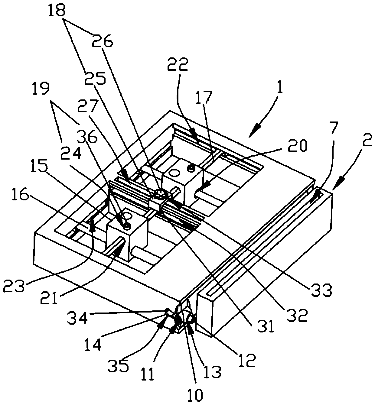
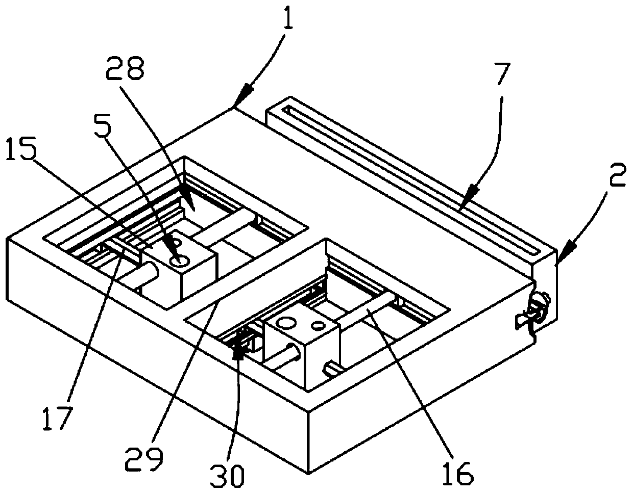
[0029] Such as Figure 1-Figure 5 As shown, the present invention discloses a distal femoral osteotomy guiding device for knee joint replacement, which includes a fixed part 1 and an oscillating saw guide part 2 installed on the fixed part 1. The fixed part 1 is provided with a The locating pin socket hole 5 in which the locating pin 4 of the distal end of the femur 3 is socketed, the oscillating saw guide part 2 is provided with a guide hole 7 for guiding the oscillating saw 6 osteotomy, and the oscillating saw guide part 2 is relatively a plurality of locating pins The fixed plane 8 formed by 4 is pivotally connected in a rotatable and positioned manner. The present invention utilizes the positioning pin 4 of the existing knee joint replacement de...


PUM


Abstract

The invention discloses a femoral far-end osteotomy guide device for knee joint replacement. The device comprises a fixing part and a swing saw guide part installed on the fixing part, the fixing part is provided with positioning needle sleeving holes sleeved with positioning needles inserted in the femoral far-end, the swing saw guide part is provided with a guide hole for guiding during swing saw osteotomy, and the swing saw guide part is in pivot joint with the fixed plane formed by the positioning needles in a rotation positioning mode. According to the device, the positioning needles of an existing knee joint replacement device are used for fixing, the swing saw guide part is rotatably positioned around the fixed plane formed by the positioning needles, the angle of a swing saw inserted in the guide hole can be adjusted relative to the fixed plane, and osteotomy at different angles can be achieved, so that the device adapts to femoral structures of different patients; further recovery of the patients is achieved, and the problem is solved that the left and right parts of the leg of the patient cannot be completely symmetric.

Description

technical field [0001] The invention relates to the field of orthopedic medical devices, in particular to a distal femur osteotomy guide device for knee joint replacement, which can adjust the osteotomy angle of a pendulum saw for osteotomy. Background technique [0002] During knee replacement surgery, it is usually necessary to use a knee replacement device to perform osteotomy on the distal femur. figure 1 , the existing knee replacement device is installed and fixed by two positioning pins 4 (gram-type steel nails) (the knee joint replacement device is provided with a positioning pin sleeve hole 5 that seamlessly slides with the positioning pins), while the existing The osteotomy guide device also uses the above two positioning pins 4 for positioning, and then uses the pendulum saw to pass through the guide hole 7 of the osteotomy guide device for osteotomy. The main problems are as follows: [0003] First, because the guide hole of the existing osteotomy guide device i...

Claims


Application Information

Patent Timeline
Patent Type & Authority Applications(China)
IPC IPC(8): A61B17/15
CPCA61B17/151
Inventor 雷鹏飞
Owner XIANGYA HOSPITAL CENT SOUTH UNIV
Why Eureka
Eureka Blog
Learn More