
Stator for rotary electric machine

A technology for a rotating electrical machine and a stator, which is applied in the field of stators and can solve the problems of complicated manufacturing processes of rotating electrical machines, high manufacturing costs, and poor cooling efficiency in slots.

Active Publication Date: 2019-09-17
HONDA MOTOR CO LTD
View PDF5 Cites 5 Cited by
  • Summary
  • Abstract
  • Description
  • Claims
  • Application Information

AI Technical Summary

Problems solved by technology

[0006] However, in the method of cooling by supplying refrigerant to the outside of the stator core or the coil ends, the cooling efficiency inside the slot is not good.
[0007] In addition, in the cooling method described in Patent Document 1, the manufacturing process of the rotating electrical machine is complicated in order to insert the heat pipe into the coil bundle layer, and thus there is a problem that the manufacturing cost becomes high.
Moreover, if the size that can realize the heat transfer function of the heat pipe is considered, the coil occupancy rate in the slot will be significantly reduced

Method used


Image

  • Stator for rotary electric machine
  • Stator for rotary electric machine
  • Stator for rotary electric machine

Examples


Embodiment Construction

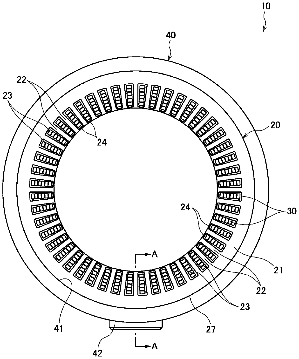
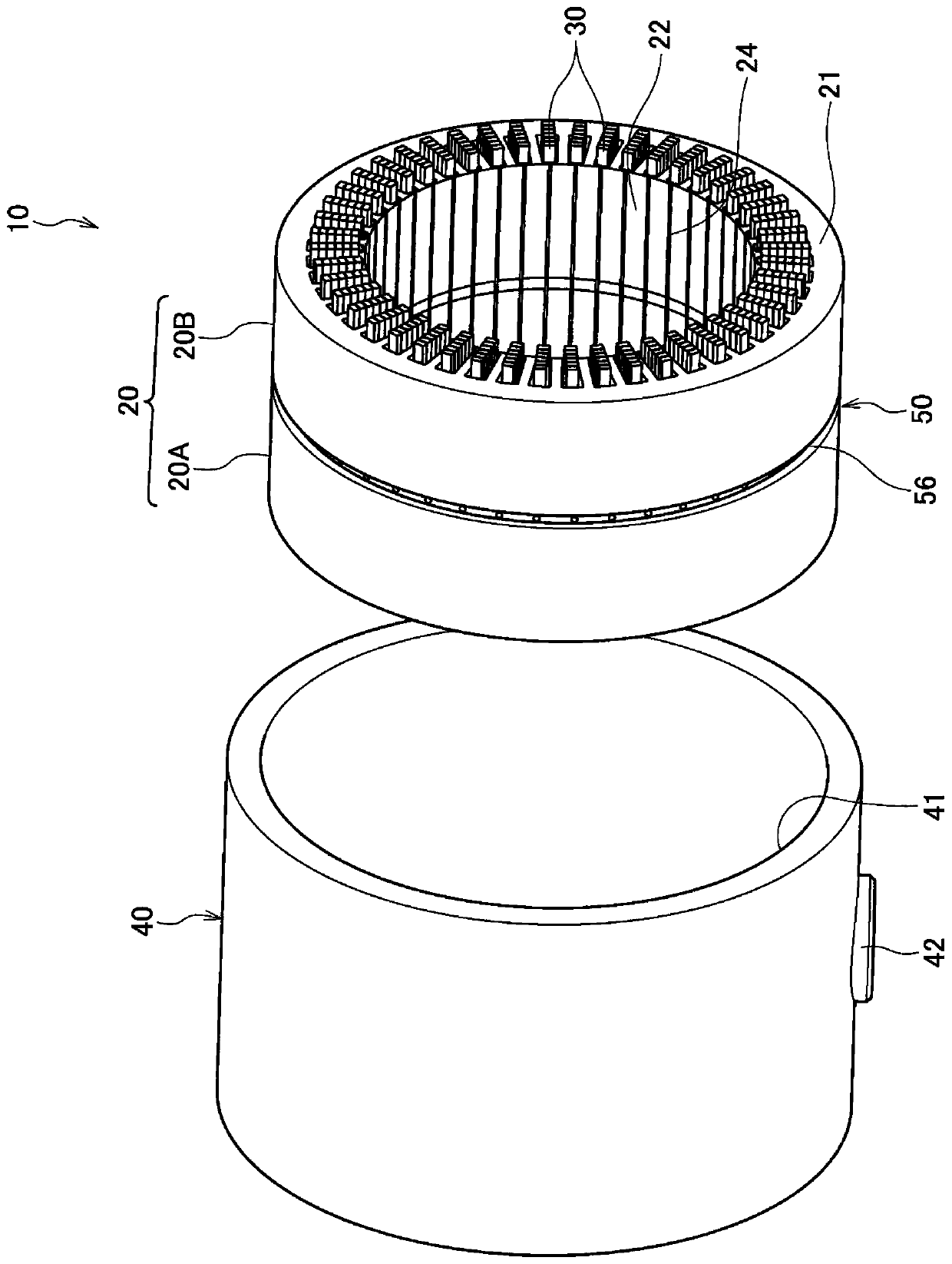
[0045] Below, refer to Figure 1 to Figure 7 , the stator 10 of the rotating electrical machine of this embodiment will be described.

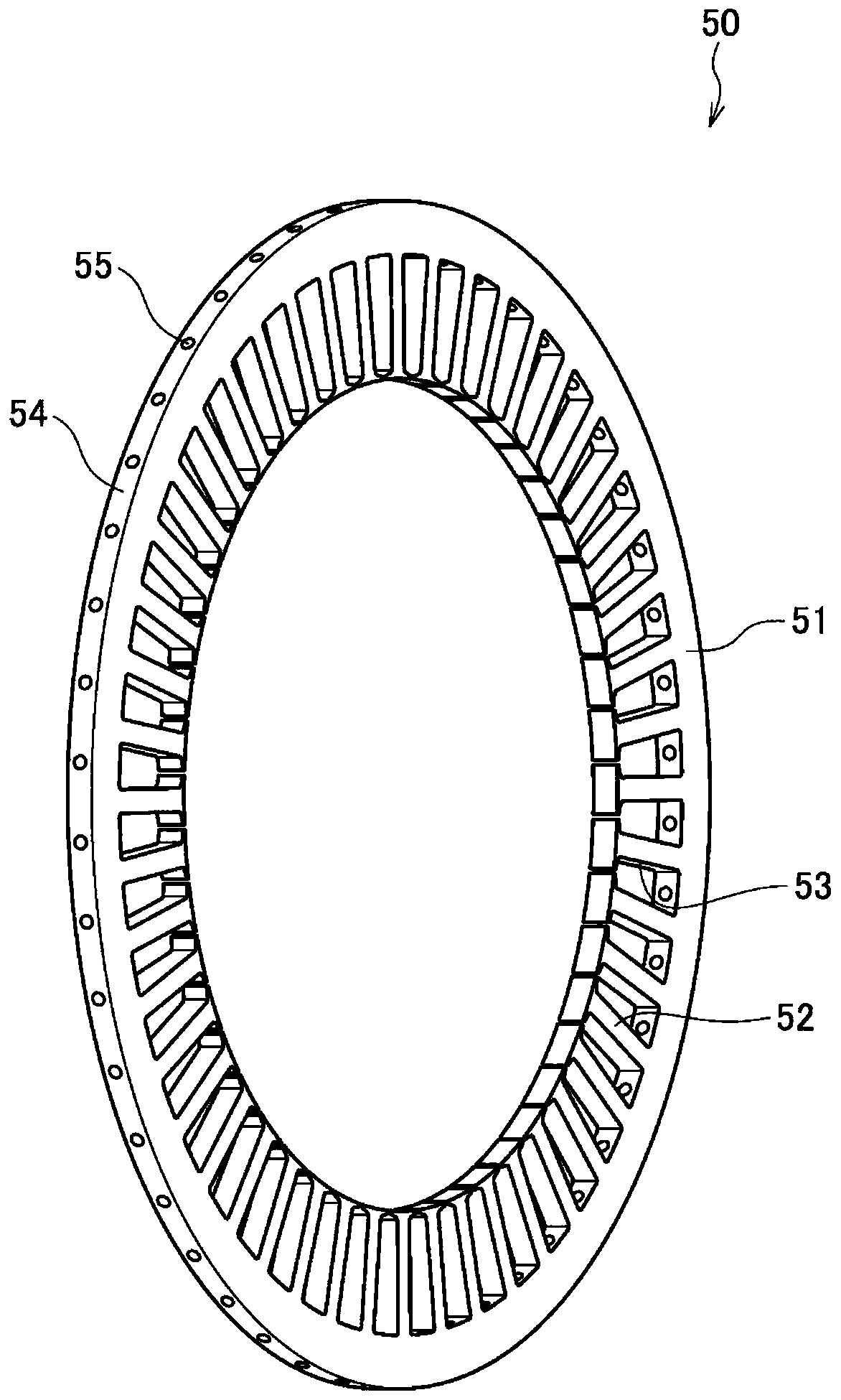
[0046] Such as figure 1 and figure 2 As shown, the stator 10 of the electric rotating machine includes: a stator core 20 ; a coil 30 ; a case 40 holding the stator core 20 ; and a refrigerant distribution plate 50 inserted into the stator core 20 .

[0047] The stator core 20 includes a pair of stator core portions 20A, 20B formed by laminating a plurality of electromagnetic steel sheets. The axial length (stack thickness) of a pair of stator core part 20A, 20B is set to be substantially the same. The pair of stator core parts 20A, 20B is formed by laminating a plurality of electromagnetic steel sheets of the same shape, and has a stator yoke 21 formed in an annular shape, a plurality of teeth 22 protruding radially inward from the stator yoke 21 , and a plurality of slots 23 formed between adjacent teeth 22 . Insulation treatment is per...


PUM


Abstract

The invention provides a stator of a rotary electric machine. Coilers arranged in a groove can be properly cooled. The stator (10) comprises a stator core (20) including an annular stator yoke (21), a plurality of teeth (22) protruding from the stator yoke (21) to an inside in a radial direction, and a plurality of slots (23) formed between adjacent teeth (22); and a plurality of coils (30) arranged in each of the slots (23). In the stator core (20), a coolant distributing plate (50) having an annular shape to surround the plurality of coils (30) from an outer circumferential side is interposed, and the coolant distributing plate (500) is provided with coolant supply portions (55) discharging a coolant toward the plurality of coils (30).

Description

technical field [0001] The present invention relates to a stator mounted in a rotating electrical machine such as an electric vehicle. Background technique [0002] The stator of the rotating electrical machine includes a stator core and a coil attached to the stator core. In order to increase the output of a rotating electrical machine, it is necessary to cool the coils that generate heat. [0003] Conventionally, as a cooling method for a rotating electrical machine, a method of supplying a refrigerant such as water or oil to the outside of the stator core or to the coil ends for cooling has been widely used. In addition, a method has been proposed in which a plate-shaped heat pipe is arranged in a coil bundle layer inserted into a slot, and the inside of the slot is cooled by heat transfer in the heat pipe (see Patent Document 1). [0004] prior art literature [0005] Patent Document 1: Japanese Patent Application Laid-Open No. H10-248211 [0006] However, in the met...

Claims


Application Information

Patent Timeline
Patent Type & Authority Applications(China)
IPC IPC(8): H02K1/14H02K5/20H02K9/19
CPCH02K1/146H02K9/227H02K5/203H02K9/197H02K1/20H02K3/24H02K1/185
Inventor 高桥忠伸田中祥雅
Owner HONDA MOTOR CO LTD
Learn More