
Crankshaft oil hole cleaning tool for cleaning machine

A crankshaft oil hole and cleaning machine technology is applied in cleaning methods and utensils, cleaning methods using liquids, chemical instruments and methods, etc. The effect of high cleaning effect

Pending Publication Date: 2019-09-20
桂林福达曲轴有限公司
View PDF0 Cites 0 Cited by
  • Summary
  • Abstract
  • Description
  • Claims
  • Application Information

AI Technical Summary

Problems solved by technology

[0002] The crankshaft is a key component in the engine. With the development of engine technology, the requirements for the crankshaft are getting higher and higher. The cleanliness of the oil hole of the crankshaft has a great impact on the engine. Generally, crankshaft products are marked on the drawings in addition to the overall cleanliness requirements. , the current high-end crankshaft products also have the weight and particle diameter requirements for the cleanliness of the oil hole. , making the engine inoperable
Generally, the crankshaft cleaning machine mainly adopts the method of overall high-pressure washing or high-pressure spot washing of the crankshaft. The integral cleaning method has better decontamination ability on the surface, but does not carry out targeted cleaning on the oil holes; while the spot washing method It is possible to spray the oil holes through programming, which needs to be done one by one, and the efficiency is not high

Method used


Image

  • Crankshaft oil hole cleaning tool for cleaning machine
  • Crankshaft oil hole cleaning tool for cleaning machine
  • Crankshaft oil hole cleaning tool for cleaning machine

Examples


Embodiment

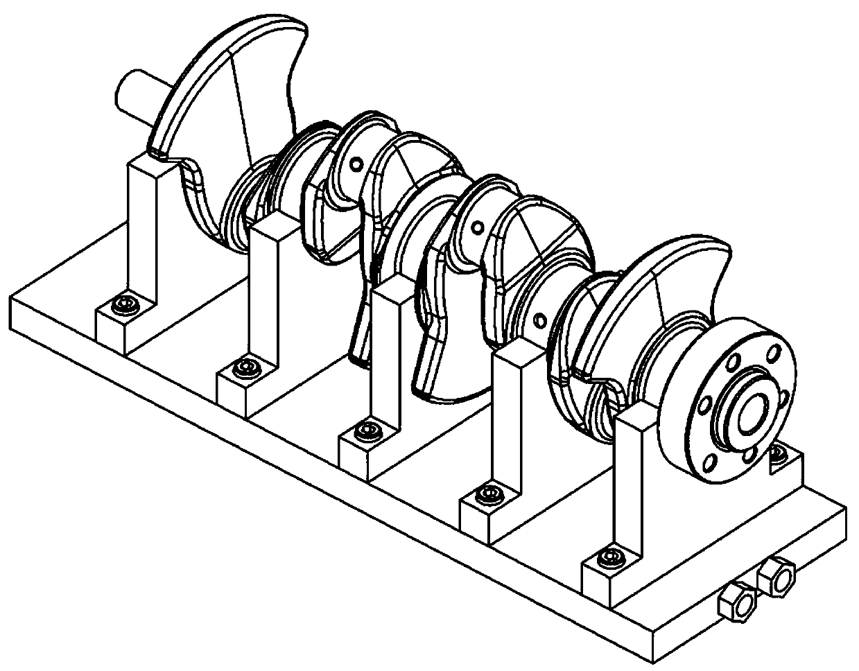
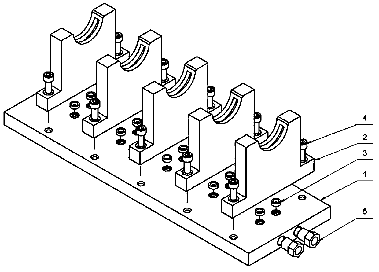
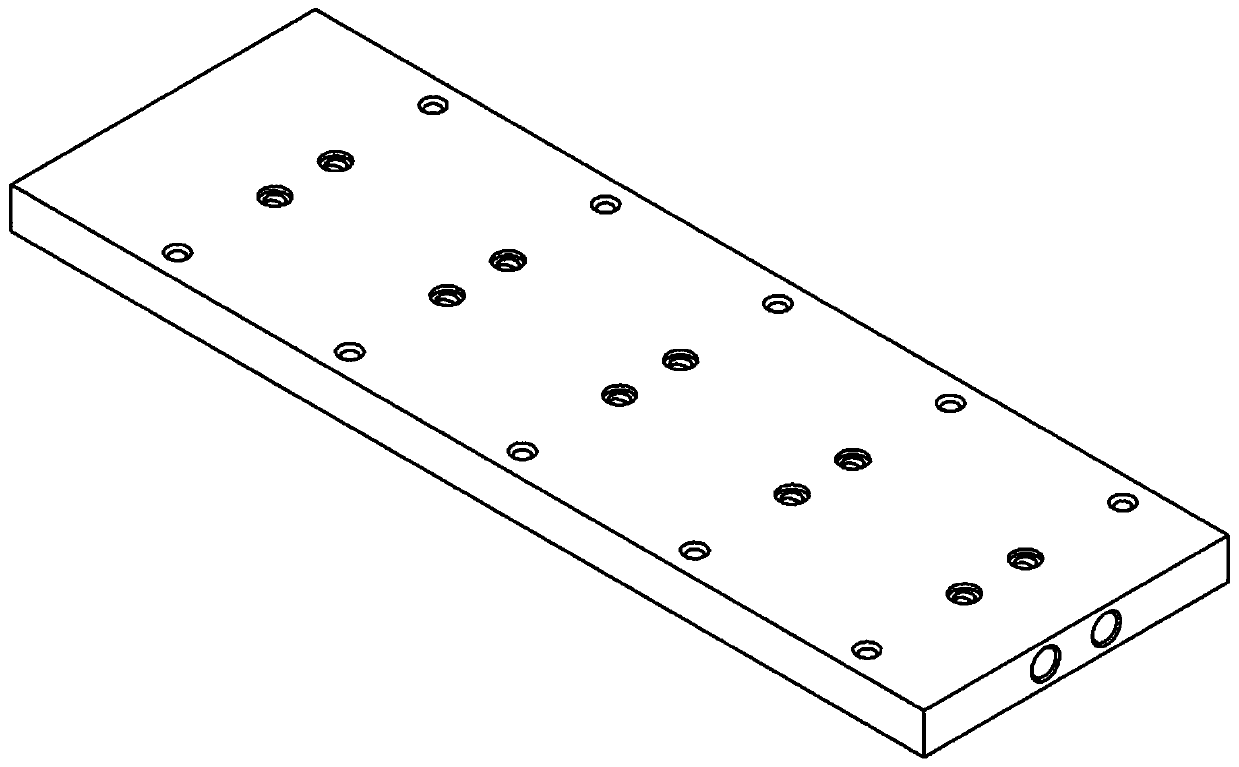
[0032] Such as Figure 1-7 As shown, a crankshaft oil hole cleaning tool for a cleaning machine includes a bottom plate 1, a support frame 2, a sealing washer 3, bolts 4 and joints 5, the bottom plate 1 is provided with a water hole 6, and a port is opened on one side of the bottom plate 1 7. The upper part of the port 7 is provided with a sink hole 8; the support frame 2 is provided with a water hole 11, the bottom is provided with a sink hole 10, and the upper arc surface is provided with a water channel 9; the sealing gasket 3 is located on the support frame. Between the hole 10 and the counterbore 8 of the base plate, it is used for the sealing of the water pipeline; the support frame 2 is fixed on the base plate 1 with bolts 4;

[0033] The using method of the present invention is as follows:

[0034] Cleaning preparation: according to the processed crankshaft product, install the corresponding crankshaft oil hole cleaning tool; place the crankshaft to be processed on th...


PUM


Abstract

The invention discloses a crankshaft oil hole cleaning tool for a cleaning machine. The crankshaft oil hole cleaning tool for the cleaning machine comprises a base plate, supporting frames, seal washers, bolts and connectors. Water holes are formed in the base plate. Through openings are formed in one face of the base plate. Countersunk holes are formed in the upper part of the through openings. Water holes are arranged in the supporting frame. Countersink holes are formed in the bottoms of the supporting frames. A water groove is formed in the upper arc face of each supporting frame. The seal washers are located between the countersunk holes of the supporting frames and the countersunk holes of the base plate and used for sealing a water pipeline. The supporting frames are fixed to the base plate through the bolts. The connection ends, with the base plate, of the connectors are provided with threads, and the connectors are used for connecting a water pipe of the cleaning machine and the cleaning tool. The crankshaft oil hole cleaning tool for the cleaning machine is simple in structure, corresponding cleaning tools can be manufactured according to different crankshaft products, type changing operation is easy and short in time, pressure cleaning is conducted for the crankshaft oil holes, the cleaning position is accurate, the cleaning efficiency is high, and the practicability is high. The crankshaft oil hole cleaning tool for the cleaning machine is suitable for use and popularization in industrial production on a large scale.

Description

technical field [0001] The invention relates to the field of auto parts manufacturing, in particular to a crankshaft oil hole cleaning tool for a washing machine. Background technique [0002] The crankshaft is a key component in the engine. With the development of engine technology, the requirements for the crankshaft are getting higher and higher. The cleanliness of the oil hole of the crankshaft has a great impact on the engine. Generally, crankshaft products are marked on the drawings in addition to the overall cleanliness requirements. , the current high-end crankshaft products also have the weight and particle diameter requirements for the cleanliness of the oil hole. , so that the engine cannot work. Generally, the crankshaft cleaning machine mainly adopts the method of overall high-pressure washing or high-pressure spot washing of the crankshaft. The integral cleaning method has better decontamination ability on the surface, but does not carry out targeted cleaning ...

Claims


Application Information

Patent Timeline
IPC IPC(8): B08B3/02B08B13/00
CPCB08B3/02B08B13/00
Inventor 黄中顺邓玉婷
Owner 桂林福达曲轴有限公司
Learn More