Flight vehicle airbag mounting device

A technology for installation devices and aircraft, which is applied in the direction of aircraft landers, etc., can solve problems such as the complex structure of aircraft airbag installation devices, and achieve the effect of meeting electromagnetic compatibility requirements and large overload

Pending Publication Date: 2019-09-20
湖南哈工蓝航科技有限公司
View PDF0 Cites 3 Cited by
  • Summary
  • Abstract
  • Description
  • Claims
  • Application Information

AI Technical Summary

Problems solved by technology

[0004] The main purpose of the present invention is to provide a kind of aircraft air bag installation device, to solve the complex structure problem of aircraft air bag installation device in the prior art

Method used


Image

  • Flight vehicle airbag mounting device
  • Flight vehicle airbag mounting device

Examples


Embodiment Construction

[0022] It should be noted that, in the case of no conflict, the embodiments of the present invention and the features in the embodiments can be combined with each other. The present invention will be described in detail below with reference to the accompanying drawings and examples.

[0023] In order to enable those skilled in the art to better understand the solutions of the present invention, the following will clearly and completely describe the technical solutions in the embodiments of the present invention in conjunction with the drawings in the embodiments of the present invention. Obviously, the described embodiments are only It is an embodiment of a part of the present invention, but not all embodiments. Based on the embodiments of the present invention, all other embodiments obtained by persons of ordinary skill in the art without making creative efforts shall fall within the protection scope of the present invention.

[0024] It should be noted that the terms "first...


PUM


Abstract

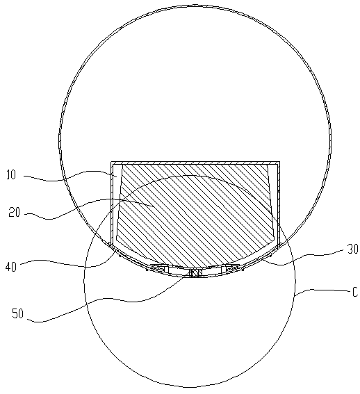
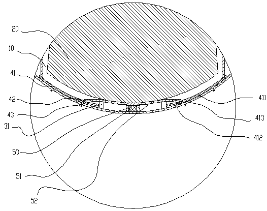
The invention provides a flight vehicle airbag mounting device. An airbag mounting chamber is arranged on a flight vehicle. An airbag is mounted in the airbag mounting chamber. The flight vehicle airbag mounting device comprises a cover plate, clamping structures and a control structure, wherein the cover plate is matched with a chamber port of the airbag mounting chamber; the clamping structures are mounted on the inner side of the cover plate; each clamping structure has a clamping position clamped to the inner wall of the chamber port and a falloff position avoiding the inner wall of the chamber port; the control structure is movably mounted on the cover plate and can abut against the clamping structures to retain the clamping structures in the clamping positions; when inflated, the airbag pushes the control structure to avoid the clamping structures so that the clamping structures can be switched from the clamping positions to the falloff positions. The flight vehicle airbag mounting device is free of magnetic control and electronic control in the whole structure, meets the requirement of an unmanned aerial vehicle for the electromagnetic compatibility and is simple, reliable and capable of meeting the requirement of the unmanned aerial vehicle for the high overload and not increasing the extra mass.

Description

technical field [0001] The invention relates to the technical field of aircraft airbag installation equipment, in particular to an aircraft airbag installation device. Background technique [0002] An important recovery method for UAVs at this stage is the combination of recovery umbrellas and buffer airbags, in which the buffer airbags can reduce the speed of the UAV from 6 to 7m / s drops to 0. The whole working process of the buffer airbag is as follows: About 5-10s after the recovery umbrella is opened, the buffer airbag starts to inflate, the airbag is inflated before the drone lands, and the airbag is deflated at the moment of landing, and the speed of the drone is reduced to 0 at the same time. The opening and closing of the airbag cover is the key in the whole process. According to the overall requirements, the opening and closing mechanism of the airbag cover needs to meet the following two basic requirements: First, the cover of the airbag should be closed firmly be...

Claims


Application Information

Patent Timeline
Patent Type & Authority Applications(China)
IPC IPC(8): B64D45/04
CPCB64D45/04
Inventor 董晓龙王猛张朝阳唐霄汉王大勇隋国发刘志伟梁先仁
Owner 湖南哈工蓝航科技有限公司
Why Eureka
Try Eureka