Glass pipe overflow down-draw molding apparatus and design method thereof

A glass tube and overflow technology, applied in glass molding, glass molding, glass manufacturing equipment, etc., to achieve the effects of small thickness deviation, excellent surface quality, and good surface characteristics

Active Publication Date: 2019-09-20
CDGM OPTICAL GLASS
View PDF8 Cites 4 Cited by
  • Summary
  • Abstract
  • Description
  • Claims
  • Application Information

AI Technical Summary

Problems solved by technology

[0003] The invention provides a glass tube overflow down-draw forming device, aiming to solve the problem of how to make a glass tube with excellent surface quality and small thickness deviation

Method used


Image

  • Glass pipe overflow down-draw molding apparatus and design method thereof
  • Glass pipe overflow down-draw molding apparatus and design method thereof
  • Glass pipe overflow down-draw molding apparatus and design method thereof

Examples


Embodiment 1

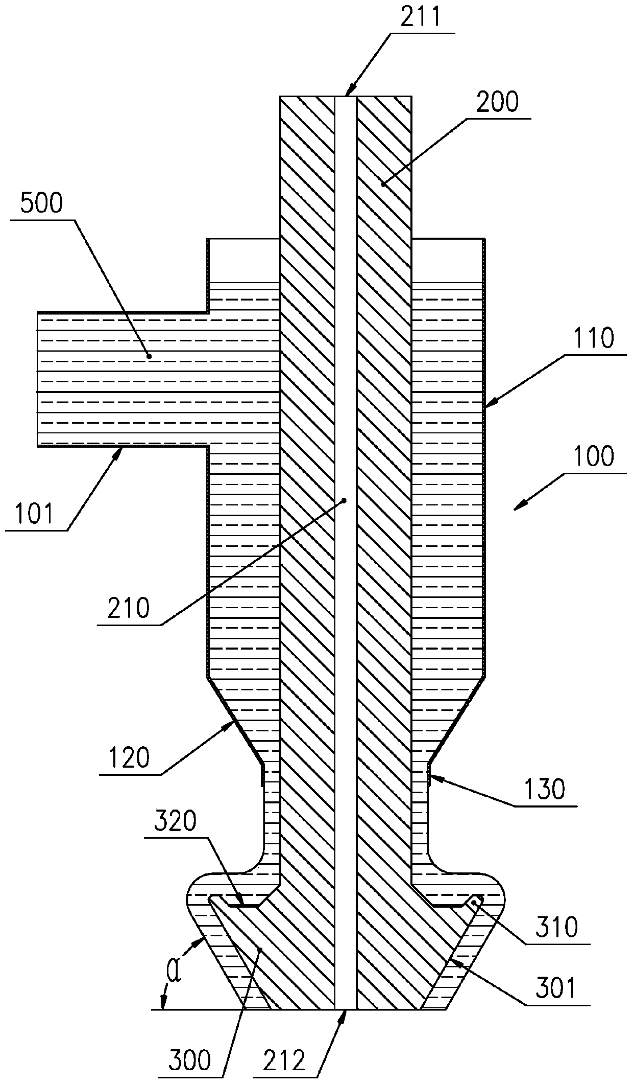
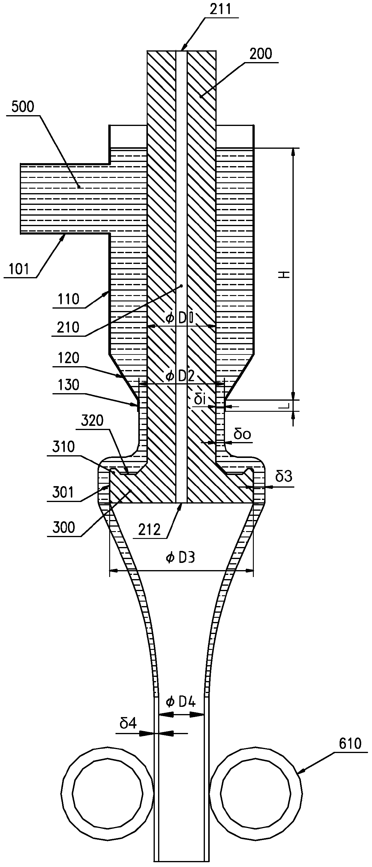
[0114] The size parameters and physical simulation experiment test parameters of an overflow glass tube overflow down-draw forming device are shown in Table 1. The viscosity of glass molding is simulated with high-viscosity silicone oil, and the experimental results are shown in 2. The glass tube overflow down-draw forming device is used to make a glass tube with a diameter of 6.0505 cm and a tube thickness of 0.1 cm; the shrinkage ratio of the tube diameter is D 3 / D 4 is 2.85.

[0115] Table 1: Adoption image 3 The design data of the structural form for simulation experiments

[0116]

[0117] Table 2: Adoption image 3 The liquid film thickness and thickness deviation test data of the simulation experiment

[0118] Numbering 1 2 3 4 5 6 7 8 Thickness (mm) 2.96 3.09 3.05 2.9 2.92 3.09 2.98 2.96 Relative deviation -1.13% 3.22% 1.88% -3.13% -2.46% 3.22% -0.46% -1.13%

[0119] During the experiment, the outlet at the lowe...

Embodiment 2

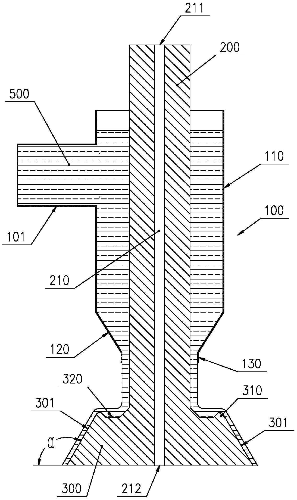
[0125] The size parameters and physical simulation test parameters of an overflow down-draw forming device for an inner overflow glass tube are shown in Table 3. The viscosity of glass molding was simulated with high-viscosity silicone oil, and the experimental results are shown in Table 4. The glass tube overflow down-draw forming device is used to make a glass tube with a diameter of 4.2266 cm and a tube thickness of 0.1 cm; the shrinkage ratio of the tube diameter is D 3 / D 4 is 3.35.

[0126] Table 3: Adoption Image 6 The design data of the structural form for simulation experiments

[0127]

[0128] Table 4: Adoption Image 6 The liquid film thickness and thickness deviation test data of the simulation experiment

[0129] Numbering 1 2 3 4 5 6 7 8 Thickness (mm) 3.71 3.70 3.59 3.73 3.58 3.64 3.53 3.51 Relative deviation 2.47% 2.03% -0.88% 2.83% -1.09% 0.37% -2.59% -3.15%

[0130] During the experiment, the outlet of...


PUM

PropertyMeasurementUnit
diameteraaaaaaaaaa

Abstract

The invention belongs to the technical field of glass pipe manufacturing, and particularly discloses a glass pipe overflow down-draw molding apparatus and a design method thereof. A purpose of the present invention is to solve the problem of how to produce a glass pipe with excellent surface quality and small thickness deviation. The glass pipe overflow down-draw molding apparatus comprises an annular material supply barrel, a cylindrical core part, and an outer overflow disc or inner overflow disc. According to the present invention, by arranging the cylindrical core part coaxial with the annular material supply barrel in the annular material supply barrel, the glass liquid accommodating ring cavity is formed between the cylindrical core part and the upper barrel body, and the narrow channel is formed between the cylindrical core part and the lower barrel body, such that the glass liquid inflowing from the glass liquid inlet can flow from the glass liquid accommodating ring cavity to the narrow channel so as to uniformly distribute the glass liquid outflowing from the narrow channel; and by arranging the outer overflow disc or inner overflow disc to overflow the glass liquid, the glass liquid can form good surface characteristic under the surface tension during the overflow so as to mold the glass pipe with excellent surface quality and small thickness deviation.

Description

technical field [0001] The invention belongs to the technical field of glass tube manufacturing, and in particular relates to a glass tube overflow down-draw forming device and a design method thereof. Background technique [0002] With the continuous advancement of science and technology and increasing innovation, the demand for high-quality optical glass tubes is also increasing, such as: optical fiber leather tubes, etc. At present, the production of optical fiber leather tubes usually undergoes cold processing after secondary drawing to meet the requirements of uniform thickness and good straightness of the glass tube; The rate is low, and the processing cost of cold processing is very high. Therefore, how to improve product quality, material utilization rate and reduce production cost is a key problem in the production of high-quality optical glass tubes. Contents of the invention [0003] The invention provides an overflow down-draw forming device for a glass tube,...

Claims


Application Information

Patent Timeline
Patent Type & Authority Applications(China)
IPC IPC(8): C03B17/04G06F17/50
CPCC03B17/04G06F30/20
Inventor 卢世峯王乃帅王培新粟勇
Owner CDGM OPTICAL GLASS
Why Eureka
Try Eureka