Threaded valve cover sealing structure with plane elastic sealing groove

A technology of elastic sealing and sealing structure, applied in the direction of valve shell structure, valve lift, valve details, etc., can solve the problems of weld stress increase, unfavorable valve sealing, failure and other problems, so as to reduce the deflection and benefit the valve disc Effect of sealing and reducing the length of the cantilever beam

Pending Publication Date: 2019-09-20
SUFA TECH IND CNNC
View PDF0 Cites 0 Cited by
  • Summary
  • Abstract
  • Description
  • Claims
  • Application Information

AI Technical Summary

Problems solved by technology

[0004] 1. The outer circle of the valve clack is guided at the place where the upper part of the valve clack matches the inner hole of the valve cover. The guiding position is on the upper side. When the valve is installed tilted or lying down, an obvious cantilever beam will be formed. When the valve clack is in the open state, Under the action of the medium, the deflection of the disc is relatively large, which is not conducive to the sealing of the valve
[0005] 2. When the temperature and pressure change, the thread will often loosen, making the tapered surface seal between the lower part of the valve cover and the valve body invalid, so that the sealing welding between the outer circle of the valve body and the valve cover will directly bear the medium pressure, making The weld is at risk of failure due to increased stress

Method used


Image

  • Threaded valve cover sealing structure with plane elastic sealing groove
  • Threaded valve cover sealing structure with plane elastic sealing groove

Examples


Embodiment Construction

[0013] Below in conjunction with accompanying drawing, the application is further described:

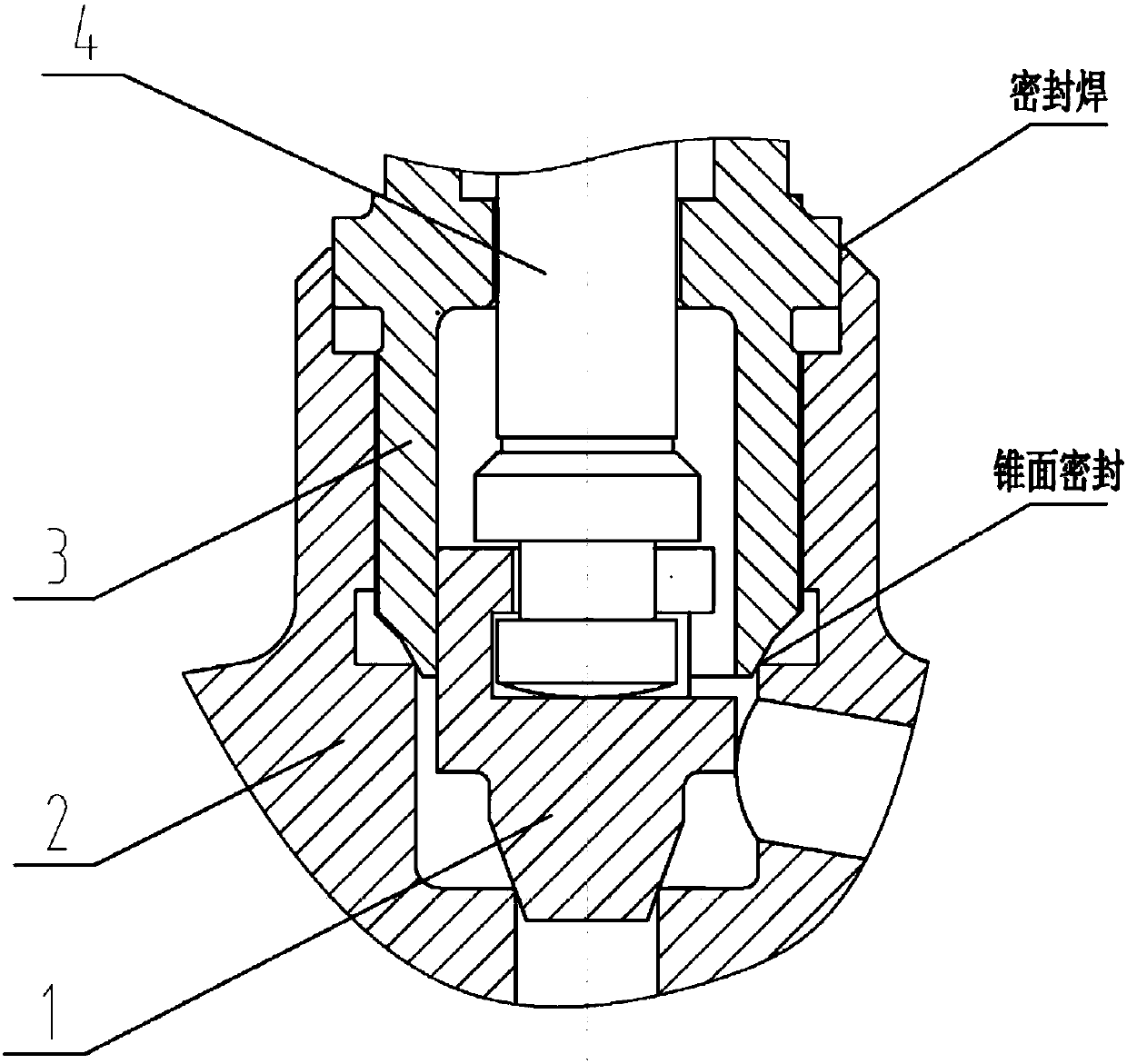
[0014] as attached figure 2 As shown, a threaded bonnet sealing structure with a planar elastic sealing groove, wherein the bottom of the bonnet is designed as a plane, which forms a plane seal with the corresponding plane of the valve body, and a groove similar to the shape of Ω is designed at the plane seal of the bonnet , and process a concave arc on the opposite side of the groove, so that an elastic Ω-shaped groove is formed. The outer circle of the valve clack is guided with the inner hole of the valve body, and the diameter of the inner hole of the valve cover is 0.5-1mm larger than the outer circle of the valve disc.

[0015] The technical features of the present invention are as follows: since the flat seal of the bonnet is designed as an elastic Ω-shaped groove, the elastic groove will automatically compensate for the thread relaxation under temperature and pressure chang...


PUM


Abstract

The invention belongs to the technical field of valves, and particularly relates to a threaded valve cover sealing structure with a plane elastic sealing groove. The threaded valve cover sealing structure comprises a valve clack, a valve body, a valve cover and a valve rod, wherein the bottom of the valve cover is a plane, a plane seal is formed by the bottom of valve cover and corresponding plane of the valve body, a groove which is similar to the omega shape is arranged in the position of the plane seal of the valve cover, a concave arc is arranged on the back surface of the groove, so that an elastic omega-shaped groove is formed. The threaded valve cover sealing structure has the remarkable effects that due to the fact that the plane seal of the bottom of the valve cover is designed into the elastic omega-shaped groove, the elastic groove can automatically compensate for thread relaxation under the change of temperature and pressure, so that the plane seal is kept effective under the change of the temperature and pressure; the pressure of a medium can increase the sealing force, so that the sealing effect of the plane seal can be enhanced; and the diameter of an inner hole of the valve cover is larger than the outer circle of the valve clack 0.5-1 mm, the inner hole of the valve cover does not have a guiding effect, the guide surface of the outer circle of the valve clack is changed into the inner hole of the valve body, so that the length of a cantilever beam guided by the valve clack is reduced, the deflection amount of the valve clack is reduced, and the sealing of the valve clack is facilitated.

Description

technical field [0001] The application belongs to the technical field of valves, and in particular relates to a threaded valve cover sealing structure with a planar elastic sealing groove. Background technique [0002] Small-diameter valves often adopt threaded bonnet sealing structure, and the common threaded bonnet sealing structure is as follows: figure 1 As shown, the bonnet is screwed into the valve body through threads, and there is a conical surface at the lower part of the bonnet. The conical surface forms the first conical surface seal after contacting the valve body. The second seal is formed by sealing welding at the center, the outer circle of the valve disc cooperates with the inner hole of the valve cover to form a guiding structure, and the valve stem drives the valve disc to move up and down through the T-shaped head. [0003] This structure has the following disadvantages: [0004] 1. The outer circle of the valve clack is guided at the place where the upp...

Claims


Application Information

Patent Timeline
Patent Type & Authority Applications(China)
IPC IPC(8): F16K27/08F16K1/38
CPCF16K27/08F16K1/38
Inventor 李军业吴辉熊冬庆
Owner SUFA TECH IND CNNC
Why Eureka
Try Eureka