Overhead underfloor heating system

A floor heating and pipeline technology, applied in the field of floor heating control, can solve the problems of floor heating water leakage is not easy to find, indoor temperature fluctuations are difficult to adjust, and adjustment lags behind, so as to prevent uneven heat transfer, save materials, and install and use immediately Effect

Active Publication Date: 2019-09-20
北京太伟宜居装饰工程有限公司 +1
View PDF17 Cites 4 Cited by
  • Summary
  • Abstract
  • Description
  • Claims
  • Application Information

AI Technical Summary

Problems solved by technology

[0006] In order to solve the above-mentioned problems and defects existing in the prior art, such as floor heating leakage, etc., which are not easy to be found, an

Method used


Image

  • Overhead underfloor heating system
  • Overhead underfloor heating system
  • Overhead underfloor heating system

Examples


Embodiment Construction

[0026] The technical solutions of the present invention will be described in further detail below with reference to the accompanying drawings and embodiments.

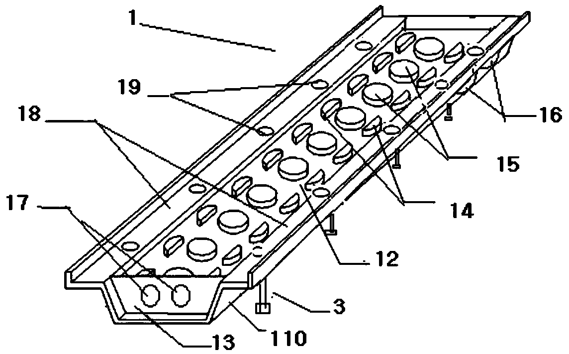
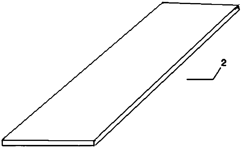
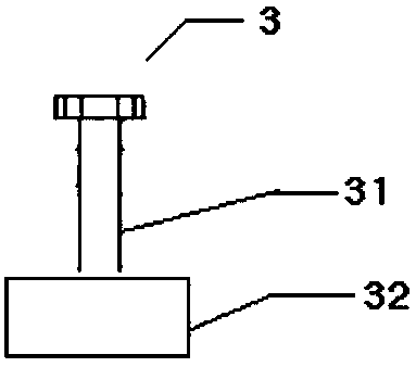
[0027] Such as Figure 1-5 As shown, the floor heating system includes: floor heating laying base layer 1, floor heating pipeline fixing layer 12, cover plate 2, partition plate 13, height adjustment rod 3, water inlet pipe through hole 17, water outlet pipe through hole 16, floor heating pipeline ( Shown among the figure) and circulating water control mechanism 4. The floor heating base layer 1 is a trapezoidal tank, the right side wall 110 of the floor heating base layer 1 is provided with a water outlet pipe through hole 16, and the left and right side walls 110 of the floor heating base layer 1 extend horizontally to form two symmetrical The table top 18, the table top 18 is evenly provided with a plurality of table top holes 19; the height adjustment rod 3 is in contact with the ground through the table top holes...


PUM


Abstract

The invention belongs to the technical field of underfloor heating and discloses an overhead underfloor heating system. The overhead underfloor heating system comprises an underfloor heating laying base layer, a underfloor heating pipe fixing layer, a cover plate, partition plates, height adjusting rods, water inlet pipe through holes, water outlet pipe through holes, an underfloor heating pipe and a circulating water control mechanism. The overhead underfloor heating system provided by the invention has the functions of fast and convenient installation, instant use after installation and constant temperature control. Different heights of the underfloor heating systems can be arranged according to different height requirements. Meanwhile, whether the underfloor heating system goes wrong or not can be checked in time according to the humidity and dehumidification can be conducted in time according to the humidity.

Description

technical field [0001] The invention belongs to the field of floor heating control, in particular to an overhead floor heating system. Background technique [0002] Floor heating is radiant floor heating. The entire floor is used as a radiator, and the heat medium in the radiant layer of the floor is used to evenly heat the entire floor. Using the heat storage of the floor itself and the law of upward radiation of heat to conduct from bottom to top, the purpose of heating is achieved. . At the same time, it has the advantages of uniform heat dissipation, comfort, appearance, safety and reliability, and long life. The existing floor heating construction is divided into wet paving construction and dry paving construction. In wet paving construction, the entire floor heating pipeline is buried under the cement floor. Wet paving construction requires backfilling, and the backfilling requirements are relatively high, occupying a large indoor area, and relatively high The backfi...

Claims


Application Information

Patent Timeline
IPC IPC(8): F24D3/14F24D19/10
CPCF24D3/141F24D19/1015
Inventor 武建振徐丽
Owner 北京太伟宜居装饰工程有限公司
Why Eureka
Try Eureka