Control method, electronic device and non-volatile computer-readable storage medium

A technology of electronic equipment and control methods, which is applied to computer components, calculations, electrical digital data processing, etc., can solve problems such as false triggering, prompting, and affecting user experience, and achieve the effects of avoiding false triggering problems and saving energy consumption

Active Publication Date: 2022-03-22
GUANGDONG OPPO MOBILE TELECOMM CORP LTD
View PDF8 Cites 0 Cited by
  • Summary
  • Abstract
  • Description
  • Claims
  • Application Information

AI Technical Summary

Problems solved by technology

However, when the fingerprint identification module is in a real-time working state, it is easy to cause a series of false triggering problems. After the false triggering, the electronic device may give unnecessary prompts to the user due to the unsuccessful fingerprint identification, etc., which seriously affects the user experience.

Method used


Image

  • Control method, electronic device and non-volatile computer-readable storage medium
  • Control method, electronic device and non-volatile computer-readable storage medium
  • Control method, electronic device and non-volatile computer-readable storage medium

Examples


Embodiment Construction

[0036] Embodiments of the present application are described in detail below, examples of which are shown in the drawings, wherein the same or similar reference numerals denote the same or similar elements or elements having the same or similar functions throughout. The embodiments described below by referring to the drawings are exemplary, are only for explaining the embodiments of the present application, and should not be construed as limiting the embodiments of the present application.

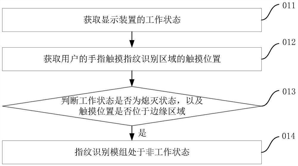
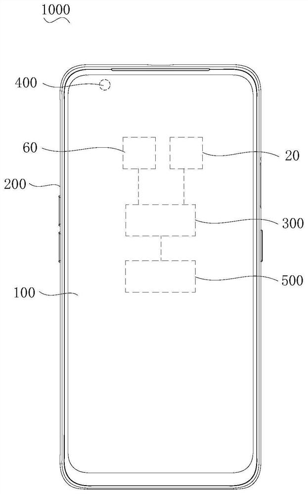
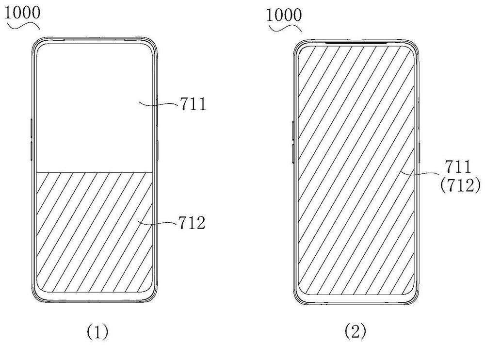
[0037] see Figure 1 to Figure 5 , the present application provides a control method for the electronic device 1000 . The electronic device 1000 includes a display device 100 . The display device 100 includes a fingerprint recognition module 20 . The fingerprint identification module 20 is located in the display area 711 of the display device corresponding to the fingerprint identification area 712 on the display device 100 . The fingerprint recognition area 712 includes an edge area 712...


PUM


Abstract

The application discloses a control method, an electronic device and a non-volatile computer-readable storage medium. The display device includes a fingerprint recognition module. The fingerprint identification module corresponds to the fingerprint identification area on the display device and is located in the display area of ​​the display device. The fingerprint identification area includes an edge area and a non-edge area except the edge area. The edge area is located at least one edge of the display area. The control method includes: obtaining the working state of the display device; obtaining the touch position where the user's finger touches the fingerprint recognition area; when the working state is off and the touch position is at the edge position, the fingerprint recognition module is in a non-working state. The control method in the embodiment of the present application determines whether to trigger the fingerprint identification module to work by judging whether the touch position of the user's finger touching the fingerprint identification area is in the edge area, which can avoid the occurrence of false triggering problems in most scenarios, and can also save electronics. The energy consumption of the equipment.

Description

technical field [0001] The present application relates to the technical field of mobile terminals, and in particular to a control method, electronic equipment, and a non-volatile computer-readable storage medium. Background technique [0002] Electronic devices are usually equipped with a fingerprint recognition function to improve the security of the use of the electronic device, such as using fingerprint recognition for unlocking, payment, and the like. In order to ensure the smoothness and convenience of users when using electronic devices, such as quickly unlocking electronic devices when receiving the user's unlocking operation, etc., the fingerprint recognition module is usually in a real-time working state, so that electronic devices can quickly identify Respond to user actions. However, when the fingerprint identification module is in a real-time working state, it is easy to cause a series of false triggering problems. After the false triggering, the electronic devi...

Claims


Application Information

Patent Timeline
Patent Type & Authority Patents(China)
IPC IPC(8): G06V40/13G06V10/96G06F1/3287G06F1/3234
CPCG06F1/3287G06F1/325G06V40/1306G06V10/96
Inventor 杨自美袁石林
Owner GUANGDONG OPPO MOBILE TELECOMM CORP LTD
Why Eureka
Try Eureka