
Steam turbine plant

A steam turbine and steam technology, which is applied to steam engine devices, mechanical equipment, engine components, etc., can solve the problem of heat energy waste of steam seal, achieve effective utilization and improve device efficiency

Active Publication Date: 2019-09-20
MITSUBISHI POWER LTD
View PDF6 Cites 0 Cited by
  • Summary
  • Abstract
  • Description
  • Claims
  • Application Information

AI Technical Summary

Problems solved by technology

[0006] However, if the excess amount of steam seal steam exchanges heat in the condenser, the heat energy of the seal steam will be wasted.

Method used


Image

  • Steam turbine plant
  • Steam turbine plant
  • Steam turbine plant

Examples


no. 1 approach

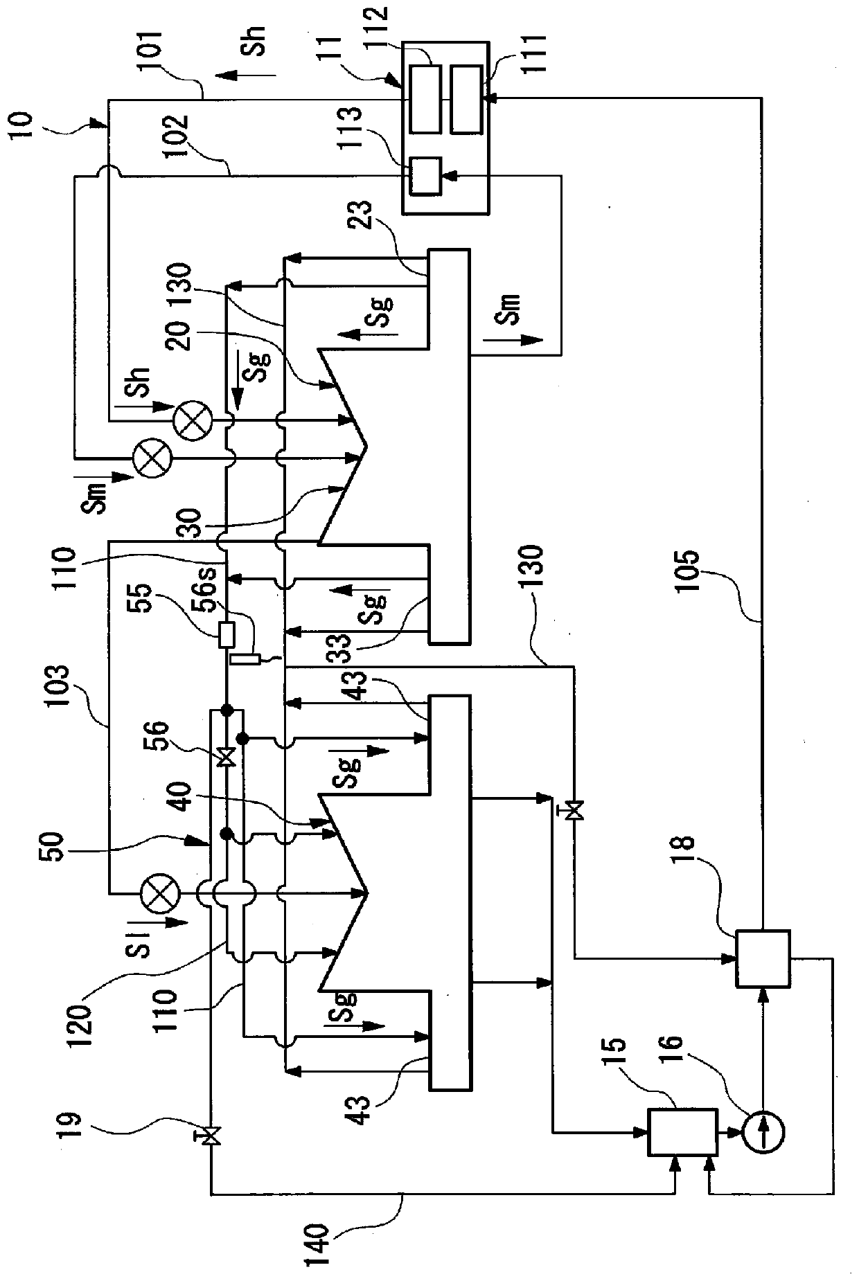
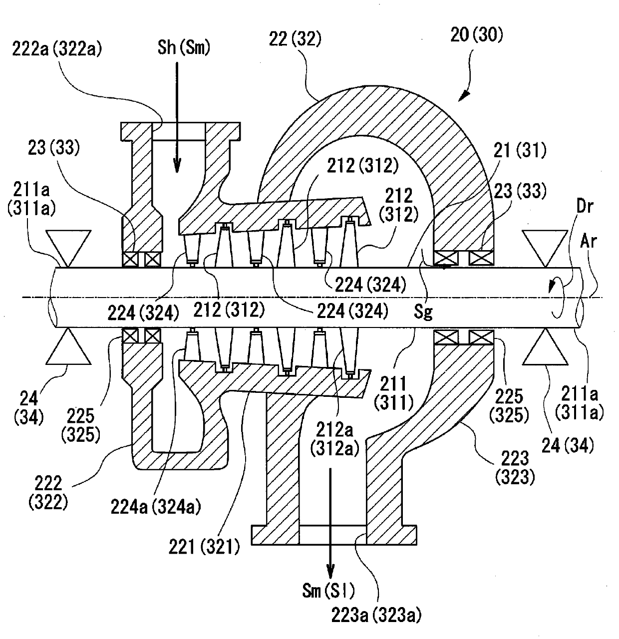
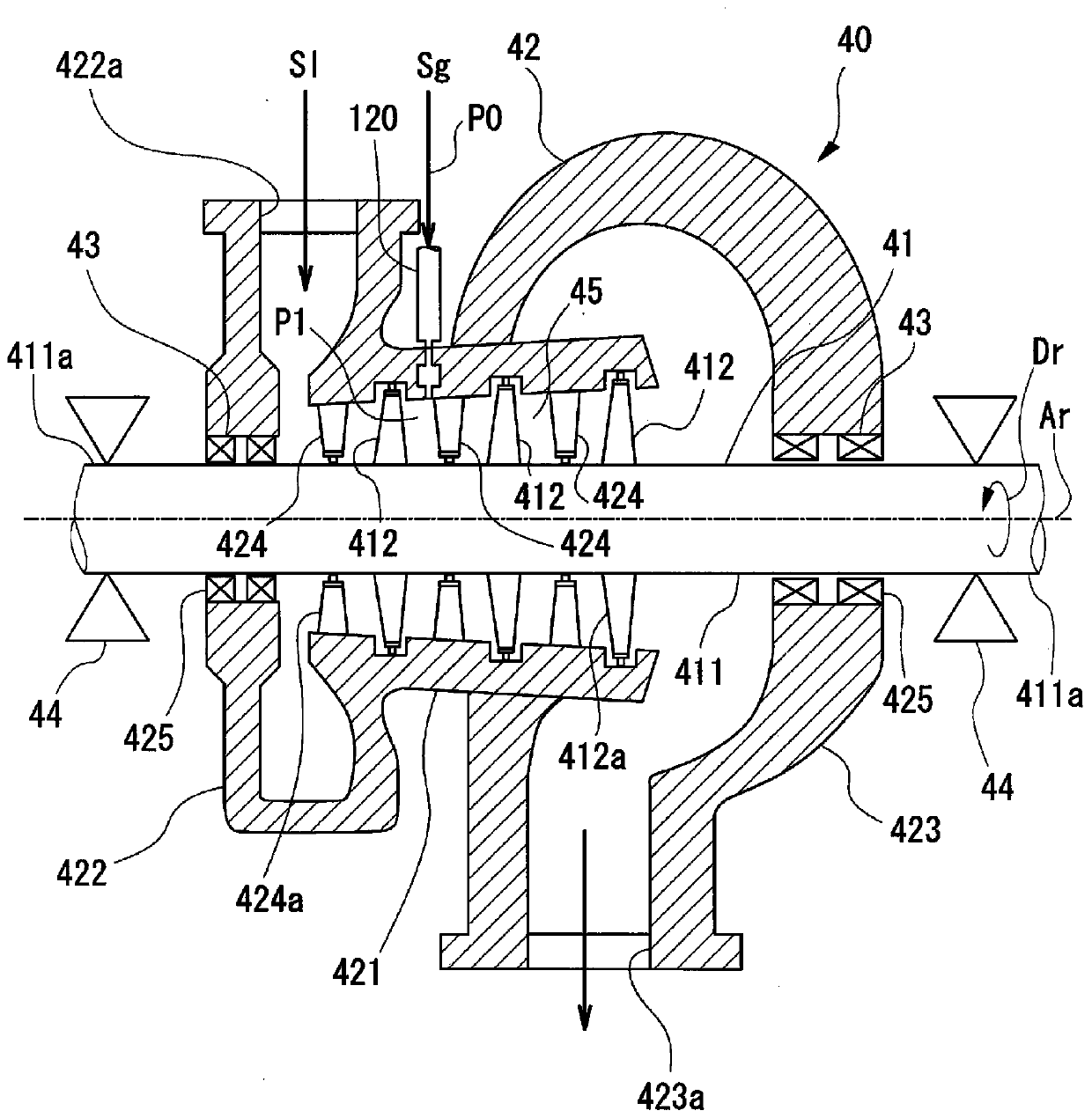
[0036] figure 1 It is a schematic diagram showing the structure of the steam turbine plant according to the first embodiment of the present invention. figure 2 It is a cross-sectional view of a high-pressure steam turbine constituting the steam turbine plant according to the first embodiment of the present invention. image 3It is a cross-sectional view of a low-pressure steam turbine constituting the steam turbine plant according to the first embodiment of the present invention. Figure 4 It is a graph showing the supply form of the seal steam at the start-up of the steam turbine plant according to the first embodiment of the present invention.

[0037] Such as figure 1 As shown, the steam turbine device 10 of this embodiment mainly includes: a boiler 11, a high-pressure steam turbine (high-pressure side steam turbine) 20, an intermediate-pressure steam turbine (high-pressure side steam turbine) 30, and a low-pressure steam turbine (low-pressure side steam turbine) 40 , c...

no. 2 approach

[0084] Next, a second embodiment of the steam turbine plant of the present invention will be described. In addition, in the following description of the second embodiment, the same reference numerals are assigned to the same configurations as those of the above-mentioned first embodiment, and description thereof will be omitted. The second embodiment differs from the first embodiment in that the seal steam Sg sent to the low-pressure steam turbine 40B through the rotor driving steam supply line 120 is supplied to a position facing the radially outer side of the moving blade row 412 . different.


PUM


Abstract

A steam turbine plant (10) is provided with a high-pressure gland portion (23), a low-pressure gland portion (43), a gland regulator line (110) and a rotor drive steam supply line (120). The high-pressure gland portion (23) seals a gap at an end portion of a high-pressure turbine rotor by supplying gland steam (Sg) into the gap. The low-pressure gland portion (43) seals a gap at an end portion of a low-pressure turbine rotor by supplying gland steam (Sg) into the gap. The gland regulator line (110) guides the gland steam (Sg) from the high-pressure gland portion (23) to the low-pressure gland portion (43). The rotor drive steam supply line (120) branches from the gland regulator line (110) and supplies part of the gland steam (Sg) to a main steam flow passage inside a low-pressure casing.

Description

technical field [0001] The present invention relates to a steam turbine plant including a plurality of steam turbines. [0002] This application claims priority based on Japanese Patent Application No. 2017-027918 for which it applied in Japan on February 17, 2017, and uses the content here. Background technique [0003] The end of the rotating shaft of the rotor of the steam turbine protrudes outside through an opening formed in the casing. In such a steam turbine, the airtightness of the end portion of the rotating shaft is ensured by allowing steam to pass through the gap between the opening of the casing and the rotating shaft. In the case of a steam turbine device including a high-pressure steam turbine and a low-pressure steam turbine, in the high-pressure steam turbine, the inside of the turbine housing becomes a higher pressure than atmospheric pressure. Therefore, at the end of the rotating shaft of the high-pressure steam turbine, steam (hereinafter, this steam i...

Claims


Application Information

Patent Timeline
IPC IPC(8): F01D11/04F01D25/24F01K7/18F16J15/447
CPCF01D11/04F01D25/24F01K7/18F16J15/44F01K7/20F01K13/02F16J15/447F16J15/4472
Inventor 西川丰治田畑创一朗高桥忠志
Owner MITSUBISHI POWER LTD
Features
  • Generate Ideas
  • Intellectual Property
  • Life Sciences
  • Materials
  • Tech Scout
  • Unparalleled Data Quality
  • Higher Quality Content
  • 60% Fewer Hallucinations
Learn More