Audio device filter modification

A technology of audio equipment and filters, applied in the direction of instruments, sensors, speech analysis, etc., can solve problems such as not being reached

Pending Publication Date: 2019-09-20
BOSE CORP
View PDF8 Cites 1 Cited by
  • Summary
  • Abstract
  • Description
  • Claims
  • Application Information

AI Technical Summary

Problems solved by technology

However, when audio equipment is used in real-world situations, beamformers based on

Method used


Image

  • Audio device filter modification
  • Audio device filter modification
  • Audio device filter modification

Examples


Embodiment Construction

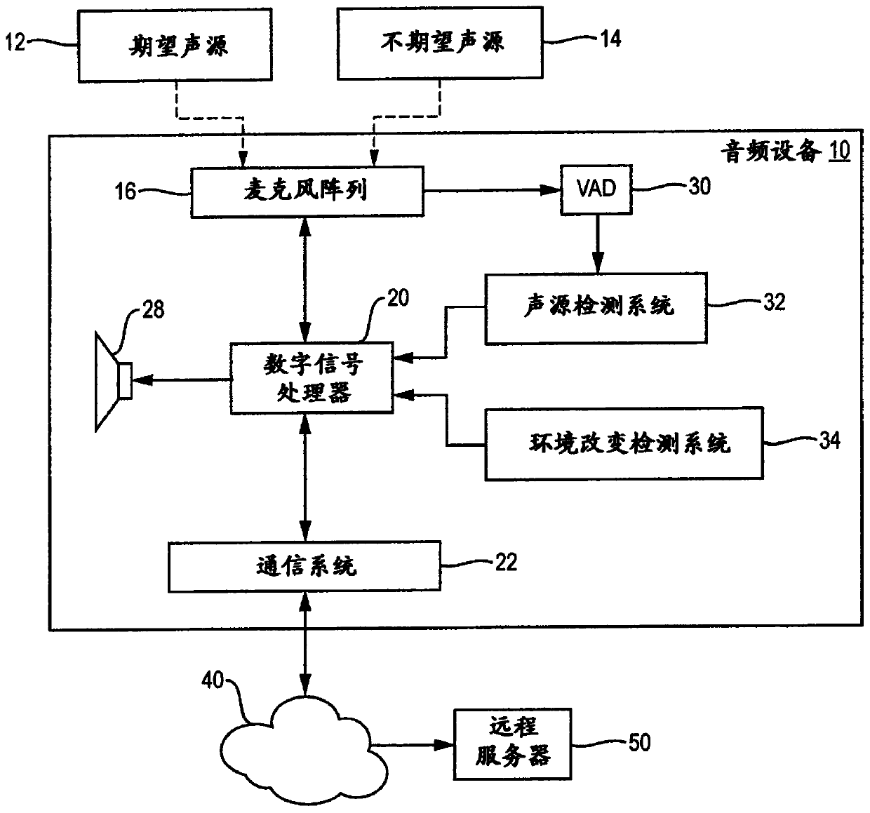
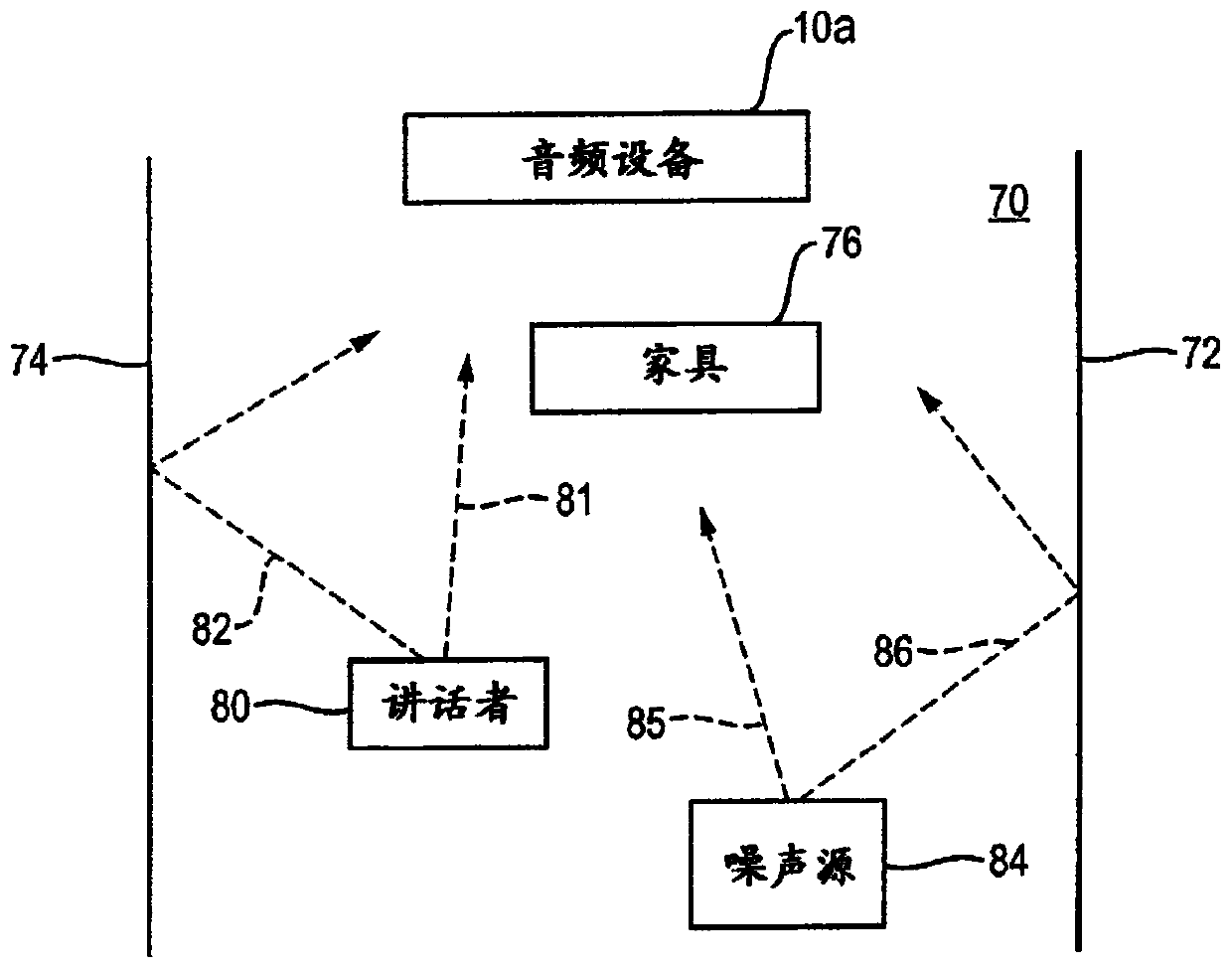
[0013] In an audio device with two or more microphones configured as a microphone array, audio signal processing algorithms or topologies, such as beamforming algorithms, are used to help distinguish desired sounds (such as human voices) from undesired sounds ( such as noise). Audio signal processing algorithms may be based on controlled recordings of idealized sound fields produced by desired and undesired sounds. These recordings are preferably, but not necessarily, taken in an anechoic environment. Audio signal processing algorithms are designed to produce optimal suppression of undesired sound sources relative to desired sound sources. However, the sound fields produced by desired and undesired sound sources in the real world do not correspond to the idealized sound fields used in the algorithm design.

[0014] With this filter modification, audio signal processing algorithms can be made more accurate for use in the real world compared to anechoic environments. This is ...


PUM


Abstract

An audio device with a number of microphones that are configured into a microphone array. An audio signal processing system in communication with the microphone array is configured to derive a plurality of audio signals from the plurality of microphones, use prior audio data to operate a filter topology that processes audio signals so as to make the array more sensitive to desired sounds than to undesired sounds, categorize received sounds as one of desired sounds or undesired sounds, and use the categorized received sounds and the categories of the received sounds to modify the filter topology.

Description

technical field [0001] The present disclosure relates to an audio device having a microphone array. Background technique [0002] Beamformers are used in audio devices to improve detection of desired sounds, such as voice commands to the device, in the presence of noise. Beamformers are often based on audio data collected in carefully controlled environments, where the data can be flagged as desired or undesirable. However, when an audio device is used in a real-world situation, a beamformer based on idealized data is only an approximation and thus may not be as effective as it should be. Contents of the invention [0003] All examples and features mentioned below can be combined in any technically possible way. [0004] In one aspect, an audio device includes a plurality of spatially separated microphones configured as a microphone array, wherein the microphones are adapted to receive sound. There is a processing system in communication with the microphone array and co...

Claims


Application Information

Patent Timeline
IPC IPC(8): G10L21/0208H04R3/00G10L21/0272G10L25/51G10L15/08G10L25/78G10L21/0216
CPCG10L2021/02087G10L25/51G10L2015/088H04R3/005G10L25/78G10L21/0208G10L21/0272G10L2021/02166H04R1/406G10L21/028G10L25/81G10L21/0216G10L25/21
Inventor A·莫吉米W·贝拉迪D·克里斯特
Owner BOSE CORP
Why Eureka
Try Eureka