Quick-moving movable spanner
An adjustable wrench and fast-moving technology, applied in the field of wrenches, can solve the problems of time-consuming, low work efficiency, and labor, and achieve the effect of shortening the opening and closing time and improving work efficiency
Inactive Publication Date: 2019-09-24
徐州光森电器工具有限公司
View PDF7 Cites 0 Cited by
- Summary
- Abstract
- Description
- Claims
- Application Information
AI Technical Summary
Problems solved by technology
Method used
View moreImage
Smart ImageViewing Examples

Examples
Embodiment
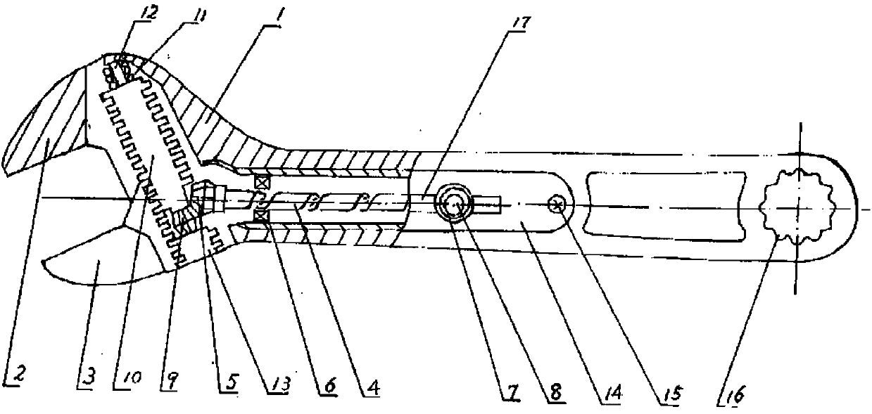
[0017] Embodiment: the present invention is made up of 14 parts, and wherein wrench body, elastic ring, jaw pin are forged parts; The bevel gear is die-casting engineering plastics, the cover plate is precision casting, and the spring is wound by hand. The present invention is a 200×24 type, that is: the body length is 200mm, and the maximum opening of the jaw is 24mm.
Login to view more PUM
 Abstract
The invention discloses a quick-moving movable spanner. A spanner body is internally provided with a quick driving mechanism composed of an active driving mechanism and a driven transmission mechanism. The active driving mechanism consists of a spiral sliding rod (4), a driving bevel gear (5), an elastic ring (6), a button (7), a gasket and pin (8), wherein one end of the spiral sliding rod (4) is provided with the driving bevel gear (5), and the other end of the spiral sliding rod (4) is fixed; the elastic ring (6) sleeves the spiral sliding rod (4) to be prevented from moving; and the button (7) is inserted into a spiral groove of the spiral sliding rod (4) and is positioned through a gasket and pin(8). The driven transmission mechanism consists of a driven bevel gear (9), a worm (10), a spring (11), a pin (12) and a plug screw (13), wherein one end of the worm (10) is fixed on the wall of the spanner body (1) through the spring (11) and the pin (12), and the other end of the worm (10) is fixed on the driven bevel gear (9), and positioned in the spanner body through the plug screw (13); the active driving mechanism and the driven transmission mechanism are mutually associated with each other through the engagement of the driving bevel gear (5) and the driven bevel gear (9); and the worm is sprayed with antirust paint.
Description
technical field [0001] The invention relates to a wrench, in particular to an adjustable wrench whose jaws can be opened and closed quickly. Background technique [0002] Now using a common adjustable wrench, the opening and closing of the jaws is completely realized by constantly rubbing the worm thread with the thumb, which is laborious, time-consuming and low in work efficiency. Contents of the invention [0003] The purpose of the present invention is to provide users with a push-pull adjustable wrench that can quickly and effectively open and close the jaws in one operation. [0004] The invention consists of four parts: a wrench body, a movable jaw, a fast driving mechanism and a cover plate. [0005] The wrench body is an integral forging, the front end of the head is a fixed jaw, the side of the head and the side of the handle are provided with notches, which respectively accommodate the movable jaw and the quick drive mechanism. And there is a ring wrench hole a...
Claims
Login to view more Application Information
Patent Timeline
 Patent Type & Authority Applications(China)
IPC IPC(8): B25B13/16B25B23/16B25B13/04C09D5/10C09D183/08
CPCB25B13/04B25B13/16B25B23/16C08K2003/0812C08K2003/2227C08K2003/2272C08K2201/011C09D5/103C09D7/61C09D7/63C09D183/08C08L91/00C08K13/02C08K3/34C08K3/22C08K3/08
Inventor 不公告发明人
Owner 徐州光森电器工具有限公司
- R&D Engineer
- R&D Manager
- IP Professional
Why Eureka
- Industry Leading Data Capabilities
- Powerful AI technology
- Patent DNA Extraction
Try Eureka
Browse by: Latest US Patents, China's latest patents, Technical Efficacy Thesaurus, Application Domain, Technology Topic.
© 2024 PatSnap. All rights reserved.Legal|Privacy policy|Modern Slavery Act Transparency Statement|Sitemap