Clamping mechanism for design drawing

A technology of clamping mechanism and design drawings, applied in drawing boards, printing and other directions, can solve the problems of inability to flexibly adjust the clamping distance, and the clamping force is not adjusted, so as to achieve a wide range of applications, improve practicability, and facilitate portability. Effect

Inactive Publication Date: 2019-09-24
SUZHOU WANDAI INFORMATION TECH CO LTD
View PDF0 Cites 1 Cited by
  • Summary
  • Abstract
  • Description
  • Claims
  • Application Information

AI Technical Summary

Problems solved by technology

[0004] The purpose of the present invention is to provide a clamping mechanism for designing drawings to solve the problems that the clamping strength cannot be adjusted and the clamping distance cannot be flexibly adjusted in the above background technology

Method used


Image

  • Clamping mechanism for design drawing
  • Clamping mechanism for design drawing
  • Clamping mechanism for design drawing

Examples


Embodiment Construction

[0019] The following will clearly and completely describe the technical solutions in the embodiments of the present invention with reference to the accompanying drawings in the embodiments of the present invention. Obviously, the described embodiments are only some, not all, embodiments of the present invention.

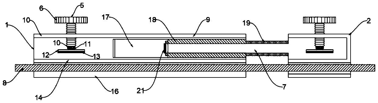
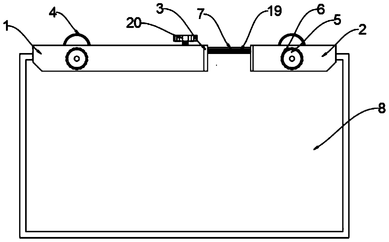
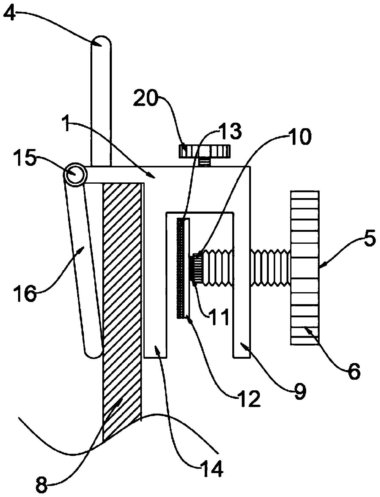
[0020] see Figure 1-3 , an embodiment provided by the present invention: a clamping mechanism for design drawings, including a main housing 1, the main housing 1 includes a first fixing plate 9, a second fixing plate 14, a clamping plate 16 and a sliding groove 17 , the second fixed plate 14 is located on one side of the first fixed plate 9, the splint 16 is located on one side of the second fixed plate 14, the inside of the sliding groove 17 is provided with a sliding rod 7, and both sides of the sliding rod 7 are provided with projections 19. One end of the sliding rod 7 is provided with a blocking block 21, the other end of the sliding rod 7 is provided with a su...


PUM


Abstract

The invention discloses a clamping mechanism for a design drawing and relates to the technical field of clamping mechanisms. Through the clamping mechanism, the problems that in the prior art, clamping force cannot be adjusted, and clamping distance cannot be adjusted flexibly are solved. A main shell comprises a first fixed plate, a second fixed plate, a clamping plate and a sliding groove. The second fixed plate is located on one side of the first fixed plate. The clamping plate is located on one side of the second fixed plate. A sliding rod is arranged in the sliding groove. An auxiliary shell is arranged at the other end of the sliding rod. One sides of the main shell and the auxiliary shell are each provided with a first adjusting bolt. One ends of the first adjusting bolts are provided with bearing outer rings. Bearing inner rings are arranged in the bearing outer rings. Fixed blocks are arranged at the other ends of the bearing inner rings. Rubber blocks are arranged at one ends of the fixed blocks. A drawing board is arranged between the second fixed plate and the clamping plate. The sliding groove is formed in the main shell, and the two sides of one end of the sliding groove are each provided with a limiting block.

Description

technical field [0001] The invention relates to the technical field of clamping mechanisms, in particular to a clamping mechanism for design drawings. Background technique [0002] With the continuous development of the social era, no matter it involves construction, machinery and other fields, it needs to go through careful design and planning before starting construction. The demand for design is gradually increasing. Today, there are many types of design equipment on the market. The style is changeable, so when doing manual drawing, it is necessary to use the clamping mechanism of the drawing, which is mainly used for clamping and fixing the design drawing. [0003] However, the existing clamping mechanism cannot be adjusted according to the thickness of the actual drawing, and it is prone to loosening or the clamping mechanism is too tight, resulting in damage to the design drawing. In addition, the existing design drawing clamping mechanism is a fixed structure, which c...

Claims


Application Information

Patent Timeline
IPC IPC(8): B43L5/02
CPCB43L5/02
Inventor 包颖玉
Owner SUZHOU WANDAI INFORMATION TECH CO LTD
Why Eureka
Try Eureka