Clutch and electric tool, garden tool and food waste disposer with clutch

A clutch and clutch block technology, applied in clutches, grain handling, friction clutches, etc., can solve problems such as small deformation, large pulling force, and small force change

Pending Publication Date: 2019-09-24
SKYBEST ELECTRIC APPLIANCE SUZHOU CO LTD
View PDF0 Cites 0 Cited by
  • Summary
  • Abstract
  • Description
  • Claims
  • Application Information

AI Technical Summary

Problems solved by technology

The movement direction of the extension spring after being stressed is consistent with its direction of force. Due to the limitation of space, it is often hoped that the extension spring will have small deformation and large tension when installed, and the stroke of the extension spring wi

Method used


Image

  • Clutch and electric tool, garden tool and food waste disposer with clutch
  • Clutch and electric tool, garden tool and food waste disposer with clutch
  • Clutch and electric tool, garden tool and food waste disposer with clutch

Examples


Embodiment Construction

[0027] The present invention will be described in detail below with reference to the embodiments shown in the accompanying drawings. However, these embodiments do not limit the present invention, and structural or functional changes made by those skilled in the art according to these embodiments are included in the protection scope of the present invention.

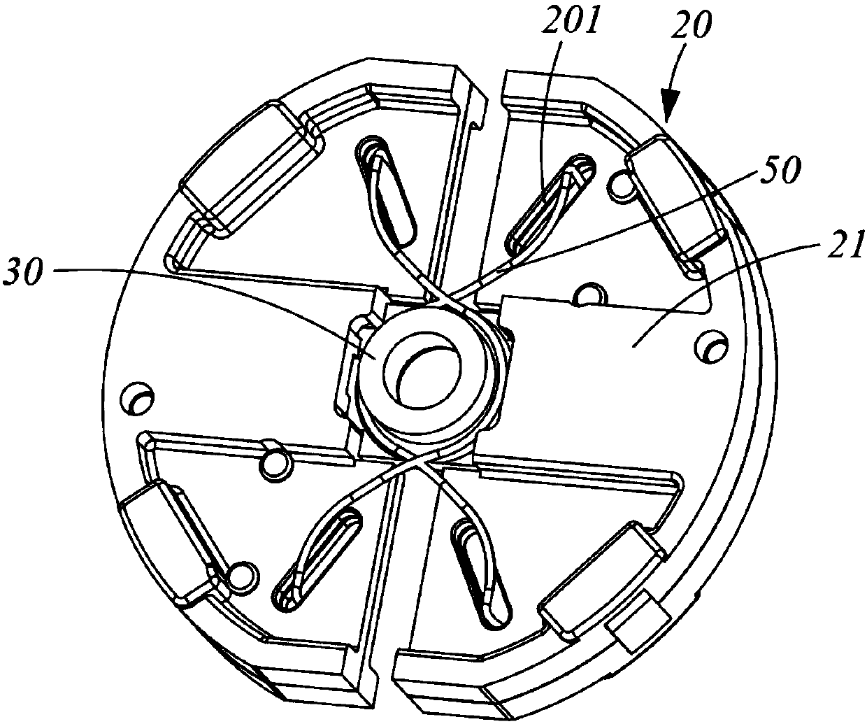
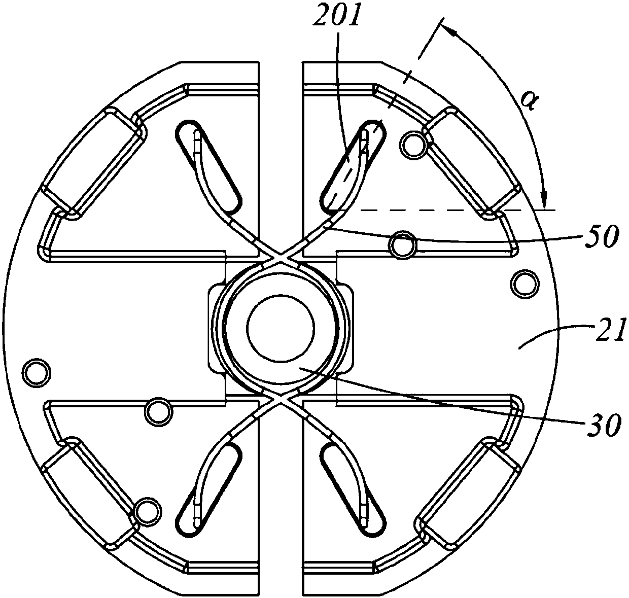
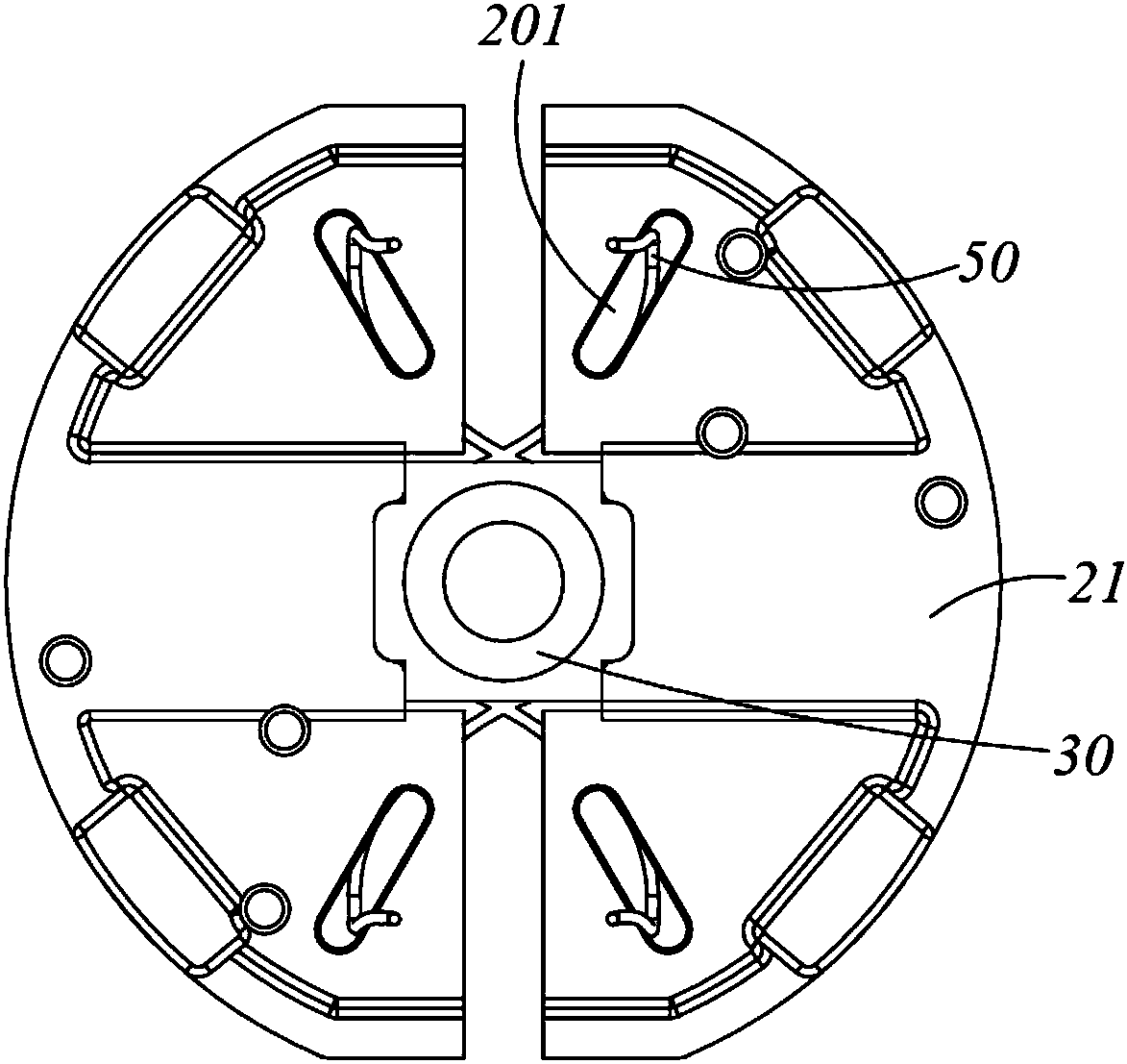
[0028] Please refer to Figure 1 to Figure 4 Shown is a preferred embodiment of the clutch of the present invention, as figure 1 and figure 2 As shown, the clutch includes a support member 30 connected to the rotating shaft, two clutch blocks oppositely arranged on both sides of the support member 30, and an elastic member 50 cooperating with the clutch block. The two clutch blocks can be arranged symmetrically with respect to the support member 30, Of course, three or more clutch blocks can also be provided, which can be uniformly arranged along the circumferential direction of the supporting member. The elastic memb...


PUM


Abstract

The present invention provides a clutch. The clutch comprises a supporting member connected with a rotating shaft, and at least two clutch blocks and elastic members fitting with the clutch blocks, wherein at least the two clutch blocks are uniformly arranged along the circumferential direction of the supporting member; the elastic members have a pre-tightening force that enables the clutch blocks to move toward the center of rotation of the supporting member; the elastic members are connected between the clutch blocks and the supporting member; the clutch blocks are provided with stroke limiting units; the stroke limiting units are configured as elongated slots; the included angle between the extending direction of each elongated slot and the moving direction of each clutch block is an acute angle; and one ends of the elastic members are clamped in the elongated slots and can move in the elongated slots under the action of centrifugal force. According to the clutch, the stroke limiting units are arranged so that the movement direction of the elastic members subjected to stress can be not in a straight line with the stress direction of the elastic members; the stroke of the clutch blocks, in the movement direction, subjected to the centrifugal force is far greater than the deformation of the elastic members; and the clutch can be applied to the condition that the free length, the stroke and the stress of the elastic members are relatively harsh.

Description

technical field [0001] The invention relates to a clutch and an operating machine with the clutch, in particular to a centrifugal clutch and an electric tool, a garden tool and a food waste disposer with the clutch. Background technique [0002] The clutch is similar to a switch, which engages or disengages the power transmission function, or performs speed limit protection by triggering the switch. The active part and the driven part of the clutch mechanism can be temporarily separated and then gradually engaged. Generally, rigid connection cannot be adopted between the driving part and the driven part of the clutch. [0003] Clutches on the market are mostly the structure in which the left and right clutch blocks are connected by extension springs or the left and right clutch blocks lean against the support block and are connected by extension springs. However, in actual use, it is often encountered that the clutch has relatively strict requirements on the length, stroke ...

Claims


Application Information

Patent Timeline
IPC IPC(8): F16D13/04F16D13/64F16D13/75B02C7/16
CPCB02C7/16B02C2201/06F16D13/04F16D13/64F16D13/75F16D2125/18
Inventor 孔钊郭宁朱光跃
Owner SKYBEST ELECTRIC APPLIANCE SUZHOU CO LTD
Why Eureka
Try Eureka