Vacuum cleaner

A vacuum cleaner and dust storage technology, applied in the field of cleaning, can solve problems such as false triggering and complex structure, and achieve the effect of avoiding the probability of false triggering and using safety.

Pending Publication Date: 2018-12-18
SKYBEST ELECTRIC APPLIANCE SUZHOU CO LTD
View PDF0 Cites 0 Cited by
  • Summary
  • Abstract
  • Description
  • Claims
  • Application Information

AI Technical Summary

Problems solved by technology

The push switch is generally arranged on the upper surface of the machine, and it is close to the front of the whole machine, so there is a risk of false triggering; there are also some vacuum cleaners equipped with a rotary switch, which is generally placed directly in front of the machine, which is not as convenient to open as the push switch, and the structure is relatively complicated.

Method used


Image

  • Vacuum cleaner
  • Vacuum cleaner
  • Vacuum cleaner

Examples


Embodiment 1

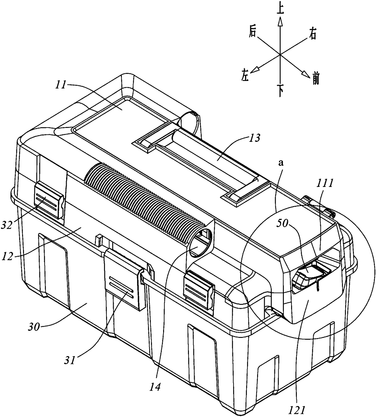
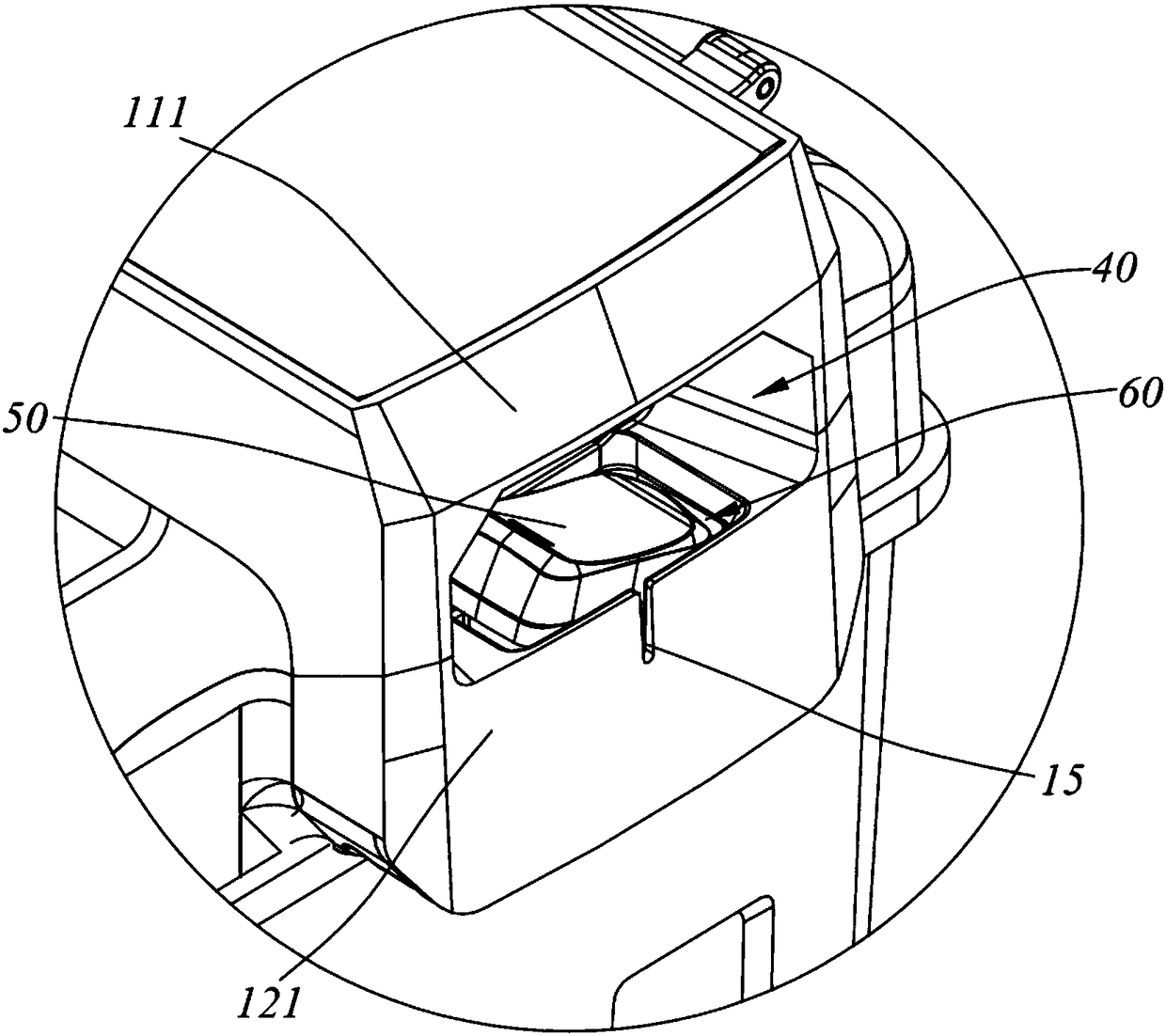
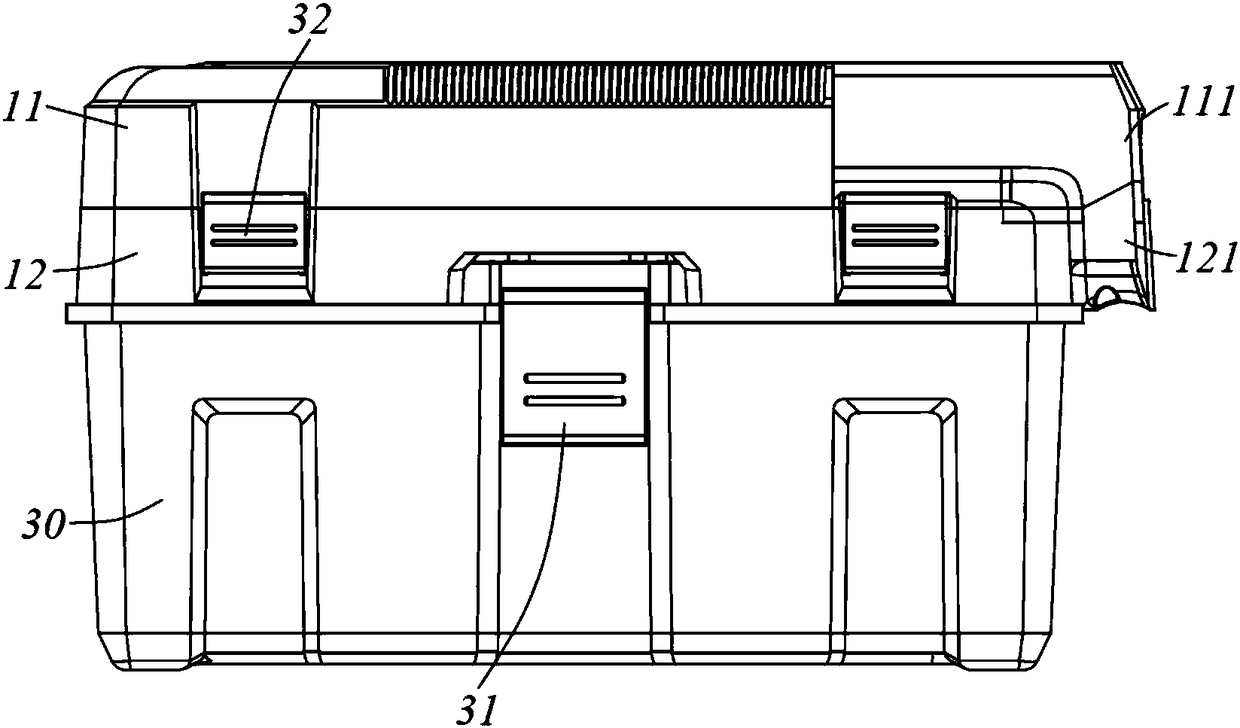
[0036] Please refer to Figure 1 to Figure 8 Shown is a preferred embodiment of the vacuum cleaner of the present invention. In this embodiment, the vacuum cleaner includes a head assembly, a dust storage cylinder 30 and a filter assembly (not shown) connected to the head assembly. Wherein, the dust storage tube 30 can be tightly fastened with the machine head assembly through the first buckle 31 , and in addition, rollers can be arranged under the dust storage tube 30 to facilitate the movement of the dust storage tube. The head assembly includes a casing and a fan arranged in the casing. A hose (not shown) can be connected to the head assembly. An air inlet 14 is arranged on the head assembly. One end of the hose is connected to the air inlet 14 of the head assembly. The other end of the hose has a suction port connected to the external environment. Under the action of the fan, the external air can be filtered from the suction port through the air inlet 14 and then discharg...

Embodiment 2

[0042] Please refer to Figure 9 to Figure 10 Shown is another preferred embodiment of the vacuum cleaner of the present invention. In this embodiment, the vacuum cleaner includes a head assembly, a dust storage cylinder 30' and a filter assembly (not shown) connected to the head assembly. Wherein, the dust storage tube 30' is sealed and detachably connected with the machine head assembly, and the bottom of the dust storage tube 30' is equipped with rollers to facilitate the movement of the vacuum cleaner. The head assembly includes a casing and a fan installed in the casing. A hose can be connected to the dust storage cylinder. An air inlet 14' is set on the dust storage cylinder 30'. One end of the hose is connected to the air inlet 14 of the dust storage cylinder 30'. 'communication, the other end of the hose has a suction port connected to the external environment, under the action of the fan, the external air can be filtered from the suction port through the air inlet 14'...

Embodiment 3

[0045] refer to Figure 12 , The difference between this embodiment and Embodiment 1 is that the trigger operation direction of the switch trigger member 50 is inclined toward the opening of the hole portion 40 . This setting not only enables the user to operate the switch trigger 50 more conveniently, but also enables the user to observe the state of the switch trigger 50 more conveniently. Other basic structures and principles of the vacuum cleaner in this embodiment are the same as those in the first embodiment, and will not be repeated here.


PUM


Abstract

The invention provides a vacuum cleaner, comprising a head assembly, a dust storage cylinder and a filter assembly arranged under the head assembly; the dust storage cylinder is detachably connected with the head assembly; the head assembly comprises a casing and a fan arranged in the casing; a switch for control the fan is arranged in the casing; a concave cavity part is arranged on a side wall of the casing; a switch trigger for starting or closing the switch is arranged in the cavity part; any part of the switch trigger is hidden in the outer contour of the casing; the cavity part comprisesan opening opened in the side wall of the casing. By setting the switch trigger in the concave part, the operator can only act on the switch actively, avoiding the probability of the whole machine triggering by mistake, and the vacuum cleaner is safer to use.

Description

technical field [0001] The invention relates to the cleaning field, in particular to a vacuum cleaner. Background technique [0002] Vacuum cleaners are widely used for cleaning in various places. Generally speaking, a vacuum cleaner usually includes an organic head assembly, a filter assembly and a barrel assembly. The filter assembly is arranged in the closed space formed by the fastening of the head assembly and the barrel assembly. Usually, the outer edge of the machine head, the outer edge of the filter assembly and the upper edge of the barrel assembly are overlapped and assembled in the axial direction, thereby effectively preventing dust from leaking out. [0003] Existing wet and dry vacuum cleaners generally start or turn off the fan by triggering a switch, and the switch generally has two forms: a push switch and a knob switch. The push switch is generally arranged on the upper surface of the machine, and it is close to the front of the whole machine, so there ...

Claims


Application Information

Patent Timeline
Patent Type & Authority Applications(China)
IPC IPC(8): A47L9/10A47L9/28A47L9/00
CPCA47L9/00A47L9/10A47L9/2857A47L9/28A47L9/102
Inventor 卞小贤刘海平吴淼
Owner SKYBEST ELECTRIC APPLIANCE SUZHOU CO LTD
Why Eureka
Try Eureka