
Dust collector

A technology for vacuum cleaners and separators, which is applied in the installation of vacuum cleaners, suction nozzles, motor fan assemblies, etc., can solve the problems of rigid structure, inflexible and labor-saving machine parts, etc., and achieve the effect of reducing damage

Pending Publication Date: 2019-11-15
SKYBEST ELECTRIC APPLIANCE SUZHOU CO LTD
View PDF0 Cites 0 Cited by
  • Summary
  • Abstract
  • Description
  • Claims
  • Application Information

AI Technical Summary

Problems solved by technology

These two structural methods are relatively rigid, and the machine parts are not flexible enough to save labor

Method used


Image

  • Dust collector
  • Dust collector
  • Dust collector

Examples


Embodiment Construction

[0037] The present invention will be described in detail below with reference to the embodiments shown in the accompanying drawings. However, these embodiments do not limit the present invention, and structural or functional changes made by those skilled in the art according to these embodiments are included in the protection scope of the present invention.

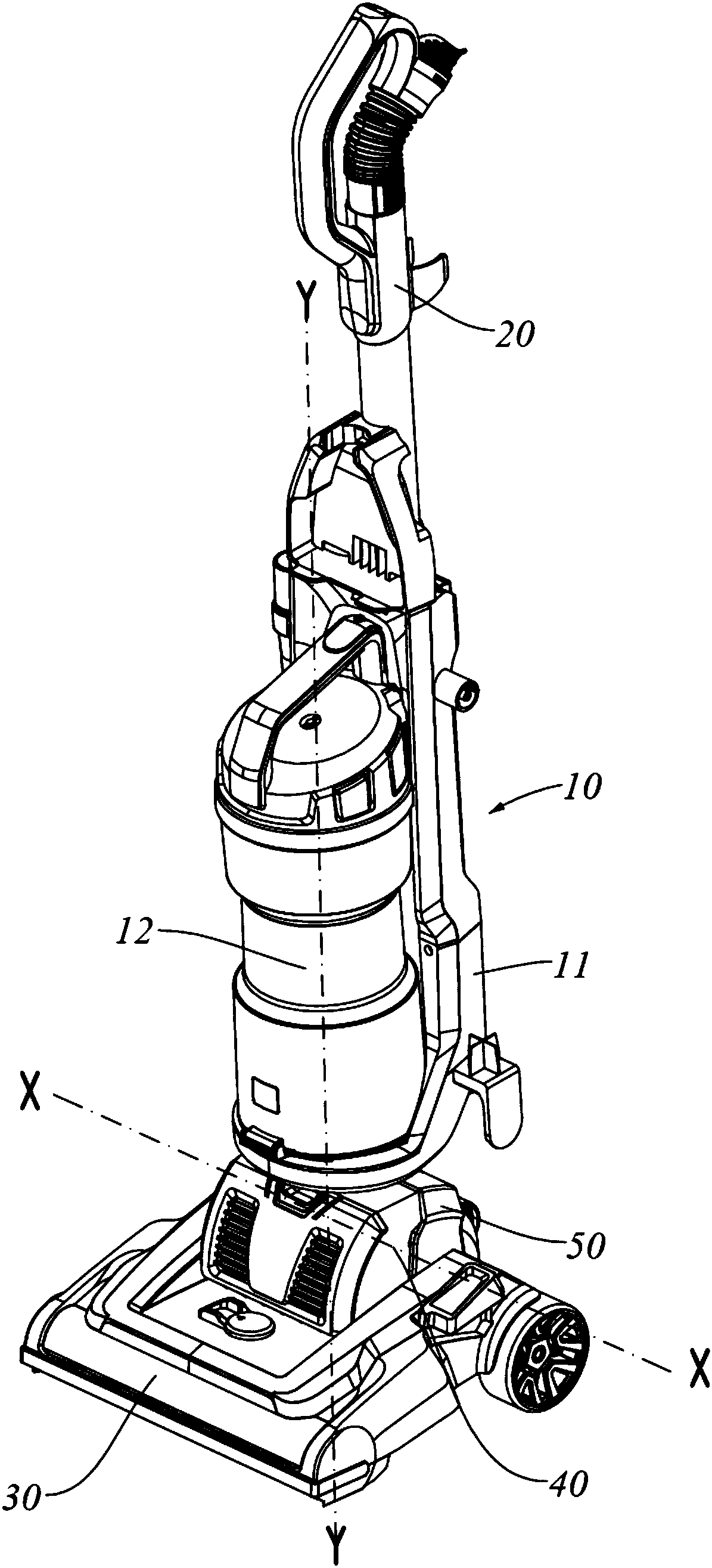
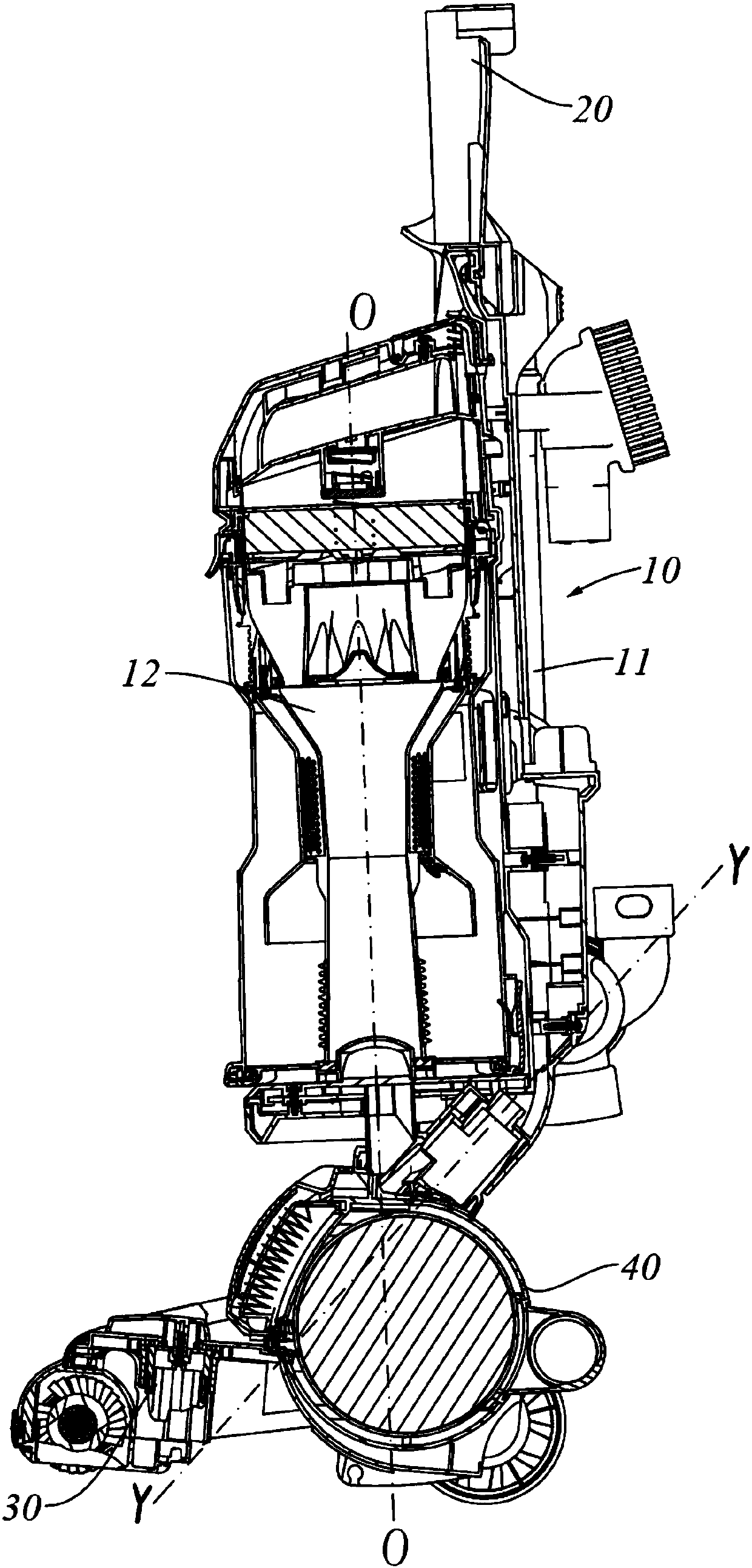
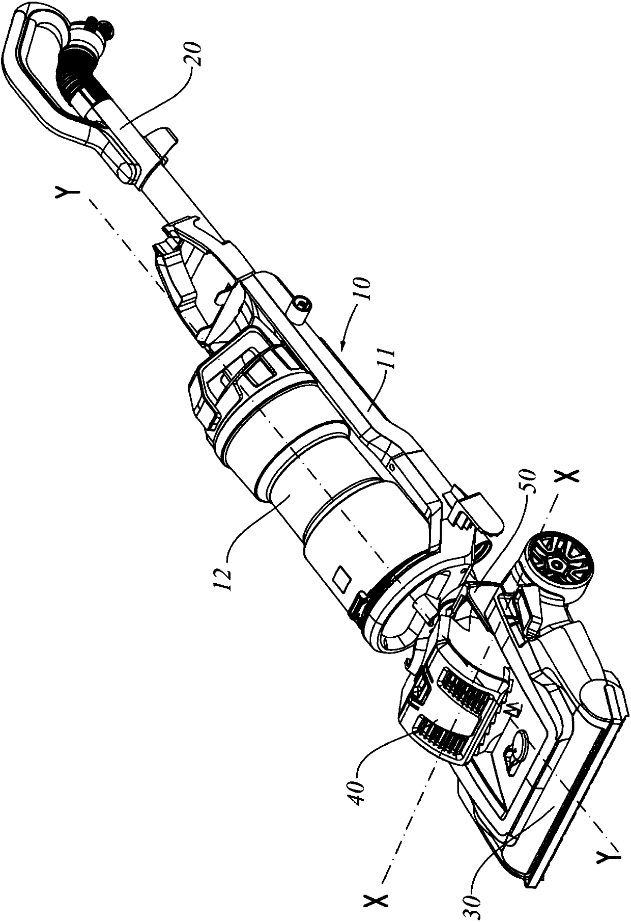
[0038] Please refer to Figure 1 to Figure 8 As shown, in a preferred embodiment of the vacuum cleaner of the present invention, the vacuum cleaner includes a body 10, a handle assembly 20 disposed at one end of the body 10, and a ground brush assembly 30 disposed at the other end of the body 10, wherein the body 10 includes a separator assembly 12 and a support separation The frame 11 of the appliance assembly 12, the handle assembly 20 is connected to one end of the frame 11, and the other end of the frame 11 is connected to the ground brush assembly 30. The ground brush assembly 30 includes a motor cover 40 and a grou...


PUM


Abstract

The invention provides a dust collector which comprises a machine body, a handle assembly and a ground brush assembly, wherein the handle assembly is arranged at one end of the machine body; the ground brush assembly is arranged at the other end of the machine body, and comprises a motor cover, a motor and a ground brush assembly main body; the motor is arranged in the motor cover; the motor coveris pivoted and connected with the ground brush assembly main body along a first axial line; the machine body is connected with the ground brush assembly through a support frame; the support frame ispivoted and connected with the ground brush assembly main body; and a pivoting shaft of the support frame is coaxial with the first axial line. Through the arrangement of the support frame pivoted andconnected with the ground brush assembly main body, an operator can realize the support frame rotation and motor cover rotation to find a comfortable and proper steering angle by operating a handle,and the easy and labor-saving steering is realized.

Description

technical field [0001] The invention relates to a vacuum cleaner, in particular to an upright vacuum cleaner. Background technique [0002] Existing vacuum cleaners have upright vacuum cleaners and horizontal vacuum cleaners. Among the upright vacuum cleaners, most of them can only move in a straight line and cannot turn, only a few can realize simple turning function, and there are two basic structures: [0003] 1. The motor cover assembly and the bracket assembly are fixed together, and the fuselage assembly is independently movable; [0004] 2. The motor cover assembly is fixed, and the bracket assembly and the fuselage assembly are fixed together for movable steering. These two structural modes are relatively rigid, and the machine parts are not flexible enough to save labor. Contents of the invention [0005] The object of the present invention is to provide a vacuum cleaner which is easy to operate. [0006] In order to achieve the purpose of the above invention,...

Claims


Application Information

Patent Timeline
Patent Type & Authority Applications(China)
IPC IPC(8): A47L5/34A47L9/00A47L9/06A47L9/28A47L9/22
CPCA47L5/34A47L9/00A47L9/009A47L9/066A47L9/28A47L9/22
Inventor 刘海平胡彬郁唯一
Owner SKYBEST ELECTRIC APPLIANCE SUZHOU CO LTD
Learn More