
An automatic blocking device and automatic blocking method for a filter separator of a gas transmission pipeline

A filter separator and gas pipeline technology, which is applied in the field of pipeline systems, can solve the problems of filter separator clogging, automatic judgment, and reduction of enterprise benefits, and achieve the effects of reducing energy loss, timely alarm speed, and improving operating efficiency

Active Publication Date: 2021-07-02
BC P INC CHINA NAT PETROLEUM CORP +2
View PDF10 Cites 0 Cited by
  • Summary
  • Abstract
  • Description
  • Claims
  • Application Information

AI Technical Summary

Problems solved by technology

[0002] During the operation of the pipeline, due to impurities in the gas, one or several filter separators are blocked, resulting in a large pressure loss when the gas passes through the filter, which eventually leads to an abnormal increase in energy consumption and reduces the benefits of the enterprise. and adversely affect the business
If you do not grasp the relevant information such as whether the filter separator is clogged in time, and deal with it in time, the clogging will continue to increase, the energy consumption will continue to increase, and eventually the filter element will be damaged.
[0003] As for whether the filter separator of the gas pipeline is blocked, the previous projects could not automatically judge, and the blockage of the filter separator could not be found in time, so that the relevant problems could only be found during fixed periodic maintenance.

Method used


Image

  • An automatic blocking device and automatic blocking method for a filter separator of a gas transmission pipeline
  • An automatic blocking device and automatic blocking method for a filter separator of a gas transmission pipeline

Examples


Embodiment 1

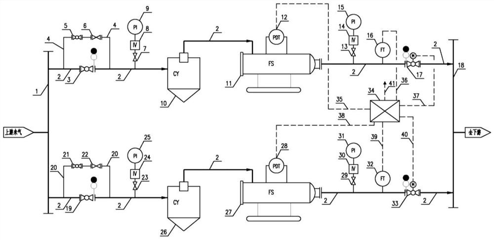
[0038] Example 1, such as figure 1 As shown, an automatic blockage detection device for a filter separator of a gas transmission pipeline according to an embodiment of the present invention includes: a first header 1 and a second header 18 connected between the first header 1 and the second header 18 Two branches are in charge of 2. A branch main pipe 2 is sequentially provided with a first valve 3, a first pressure gauge 9, a first cyclone separator 10, a first filter separator 11, a second pressure gauge 15, and a first flow transmitter from upstream to downstream. The device 16 and the first electric valve 17, the first differential pressure transmitter 12 is installed on the first filter separator 11. The other branch main pipe 2 is sequentially provided with a fourth valve 19, a third pressure gauge 25, a second cyclone separator 26, a second filter separator 27, a fourth pressure gauge 31, and a second flow transformer from upstream to downstream. Transmitter 32 and se...

Embodiment 2

[0044] Embodiment 2, a gas pipeline filter separator automatic blocking detection method for a gas pipeline filter separator automatic blocking detection device, including:

[0045] Step 1: Install an automatic blockage judgment device for a gas pipeline filter separator between the upstream and downstream of the gas pipeline. The automatic blockage detection device for the filter separator of the gas transmission pipeline is as described in Embodiment 1, and will not be described in detail here.

[0046] Step 2, start the automatic blockage judgment device of the filter separator of the gas transmission pipeline, and the control system sets the pressure difference alarm value of the differential pressure transmitter on the two branch main pipes 2 and the flow difference alarm value of the flow transmitter. Specifically, it includes the differential pressure alarm value of the first differential pressure transmitter 12 and the second differential pressure transmitter 28 , and ...


PUM


Abstract

The invention discloses an automatic blockage judgment device for a filter separator of a gas transmission pipeline, comprising: a first manifold, a second manifold and two branch main pipes between them; each branch main pipe is sequentially provided with a valve , a pressure gauge, a cyclone separator, a filter separator, a pressure gauge, a flow transmitter and an electric valve, the differential pressure transmitter is mounted on the filter separator; differential pressure transmitter, flow transmitter Both the controller and the electric valve are connected to the junction box, and the junction box is connected to the control system. The invention also discloses a method for automatically judging blockage of the filter separator of the gas transmission pipeline. The invention has beneficial effects: it can monitor in real time whether the filter separator of the gas transmission pipeline is blocked, the alarm speed is timely and the accuracy is high, the operation efficiency of the gas transmission pipeline is improved, and energy consumption is reduced.

Description

technical field [0001] The invention relates to the technical field of pipeline systems, in particular to an automatic blocking detection device and an automatic blocking detection method for a filter separator of a gas transmission pipeline. Background technique [0002] During the operation of the pipeline, due to impurities in the gas, one or several filter separators are blocked, resulting in a large pressure loss when the gas passes through the filter, which eventually leads to an abnormal increase in energy consumption and reduces the benefits of the enterprise. And brought adverse effects to the enterprise. If you do not grasp the relevant information such as whether the filter separator is clogged in time, and deal with it in time, the clogging will continue to increase, the energy consumption will continue to increase, and eventually the filter element will be damaged. [0003] As for whether the filter separator of the gas transmission pipeline is blocked, the pre...

Claims


Application Information

Patent Timeline
Patent Type & Authority Patents(China)
IPC IPC(8): B01D46/00
CPCB01D46/0086
Inventor 聂中文黄晶赵国辉王振业公维龙王树祺刘芳芳
Owner BC P INC CHINA NAT PETROLEUM CORP
Learn More